Datasheet4U Logo Datasheet4U.com

LMK04806 - Low-Noise Clock Jitter Cleaner

Download the LMK04806 datasheet PDF. This datasheet also covers the LMK04803 variant, as both devices belong to the same low-noise clock jitter cleaner family and are provided as variant models within a single manufacturer datasheet.

General Description

The LMK0480x family is the industry's highest performance clock conditioner with superior clock jitter cleaning, generation, and distribution with advanced

Key Features

  • 1 Ultra-Low RMS Jitter Performance.
  • 111 fs RMS Jitter (12 kHz to 20 MHz).
  • 123 fs RMS Jitter (100 Hz to 20 MHz).
  • Dual Loop PLLatinum™ PLL Architecture.
  • PLL1.
  • Integrated Low-Noise Crystal Oscillator Circuit.
  • Holdover Mode when Input Clocks are Lost.
  • Automatic or Manual Triggering/Recovery.
  • PLL2.
  • Normalized PLL Noise Floor of.
  • 227 dBc/Hz.
  • Phase Detector Rate up to 155 MHz.
  • OSCin Frequ.

📥 Download Datasheet

Note: The manufacturer provides a single datasheet file (LMK04803-etcTI.pdf) that lists specifications for multiple related part numbers.

Full PDF Text Transcription (Reference)

The following content is an automatically extracted verbatim text from the original manufacturer datasheet and is provided for reference purposes only.

View original datasheet text
Product Folder Sample & Buy Technical Documents Tools & Software Support & Community LMK04803, LMK04805, LMK04806, LMK04808 SNAS489K – MARCH 2011 – REVISED DECEMBER 2014 
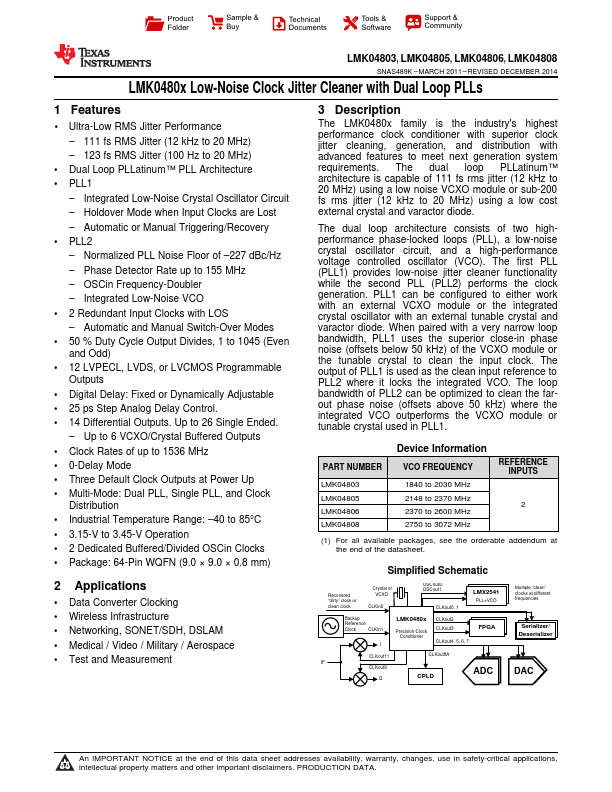
LMK0480x Low-Noise Clock Jitter Cleaner with Dual Loop PLLs 1 Features •1 Ultra-Low RMS Jitter Performance – 111 fs RMS Jitter (12 kHz to 20 MHz) – 123 fs RMS Jitter (100 Hz to 20 MHz) • Dual Loop PLLatinum™ PLL Architecture • PLL1 – Integrated Low-Noise Crystal Oscillator Circuit – Holdover Mode when Input Clocks are Lost – Automatic or Manual Triggering/Recovery • PLL2 – Normalized PLL Noise Floor of –227 dBc/Hz – Phase Detector Rate up to 155 MHz – OSCin Frequency-Doubler – Integrated Low-Noise VCO • 2 Redundant Input Clocks with LOS – Automatic and Manual Switch-Over Modes • 50 % Duty Cycle Output Divides, 1 to 1