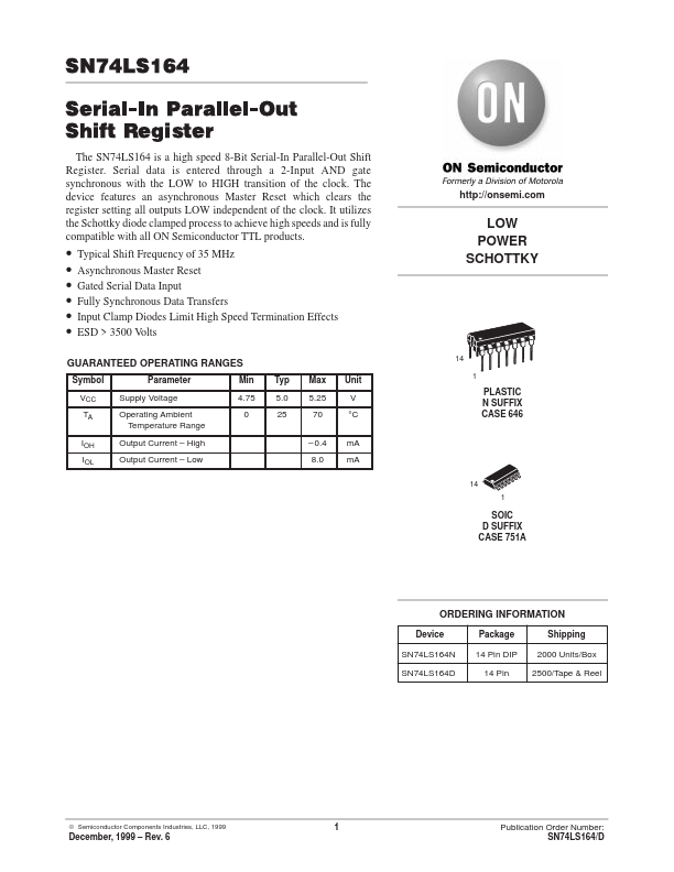
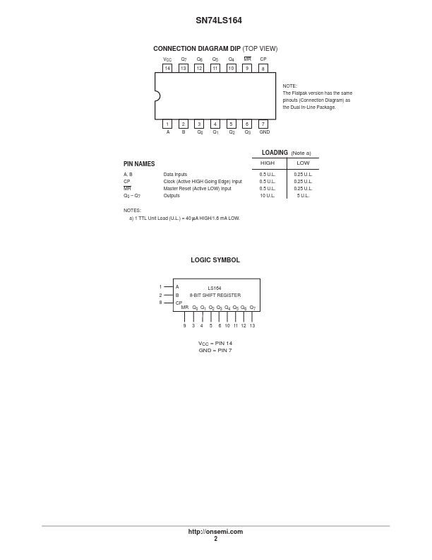
DESCRIPTION
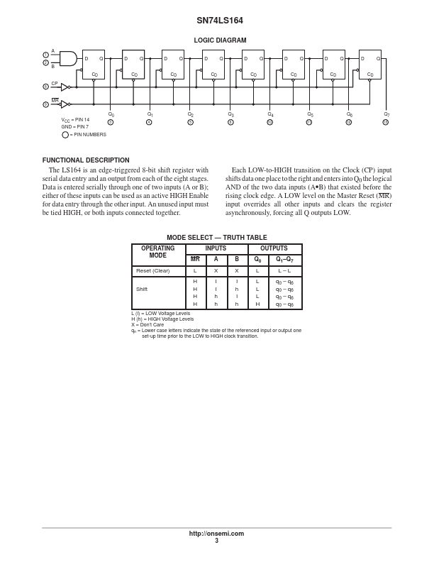
Data is entered serially through one of two inputs (A or B); either of these inputs can be used as an active HIGH Enable for data entry through the other input. An unused input must be tied HIGH, or both inputs connected together. A LOW level on the Master Reset (MR) input overrides all other inputs and clears the register asynchronously, forcing all Q outputs LOW. MODE SELECT — TRUTH TABLE OPERATING MODE Reset (Clear) Shift INPUTS MR L H H H H A X I I h h B X I h I h OUTPUTS Q0 L L L L H Q1–Q7 L–L q0 – q6 q0 – q6 q0 – q6 q0 – q6 L (l) = LOW Voltage Levels H (h) = HIGH Voltage Levels X = Don’t Care qn = Lower case letters indicate the state of the referenced input or output one qn = set-up time prior to the LOW to HIGH clock transition. 3 SN74LS164 DC CHARACTERISTICS OVER OPERATING TEMPERATURE RANGE (unless otherwise specified) Limits Symbol VIH VIL VIK VOH Parameter Input HIGH Voltage Input LOW Voltage Input Clamp Diode Voltage Output HIGH Voltage 2.7 – 0.65 3.5 0.25 VOL O... onsemi