onsemi FDS3672
N-Channel MOSFET
| Part No. | FDS3672 |
|---|---|
| Datasheet | FDS3672 Download |
| Manufacturer |  onsemi |
| Description | N-Channel MOSFET |
| Buy | Stock & Price |

FEATURES
● rDS(ON) = 19 mW (Typ.), VGS = 10 V, ID = 7.5 A● Qg(tot) = 28 nC (Typ.), VGS = 10 V
● Low Miller Charge
● Low QRR Body Diode
● Optimized Efficiency at High Frequencies
● UIS Capability (Single Pulse and Repetitive Pulse)
● Pb−Free and Halide Free
APPLICATIONS
● DC−DC Converters and Off−Line UPS● Distributed Power Architecture and VRMs
● Primary Switch for 24 V and 48 V Systems
● High Voltage Synchronous Rectifier MOSFET
MAXIMUM RATINGS
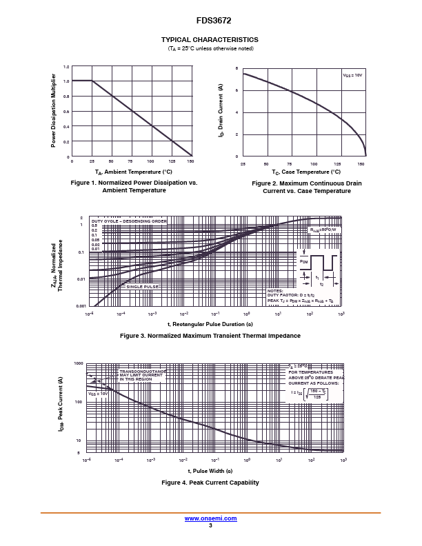
(TA = 25°C unless otherwise noted.) Symbol Parameter Ratings Unit VDSS Drain to Source Voltage 100 V VGS Gate to Source Voltage ±20 V ID Drain Current A Continuous (TA = 25°C, VGS = 10 V, 7.5 RqJA = 50°C/W) Continuous (TA = 100°C, VGS = 10 V, 4.8 RqJA = 50°C/W) Pulsed Figure 4 EAS Single Pulse Avalanche Energy (Note 1) PD Power Dissipation Derate above 25°C 416 mJ 2.5 W 20 mW/°C TJ, TSTG Operating and Storage Junction Temperature Range −55 to +150 °C Stresses exceeding those listed in theMAXIMUM RATINGS
table may damage the device. If any of these limits are exceeded, device functionality should not be assumed, damage may occur and reliability may be affected.