AOW66412 Overview
The value of RθJA is measured with the device mounted on 1in2 FR-4 board with 2oz. Copper, in a still air environment with TA =25°C. The Power dissipation PDSM is based on R θJA t≤ 10s.
AOW66412 datasheet by Alpha & Omega Semiconductors.
| Part number | AOW66412 |
|---|---|
| Datasheet | AOW66412-AlphaOmegaSemiconductors.pdf |
| File Size | 313.85 KB |
| Manufacturer | Alpha & Omega Semiconductors |
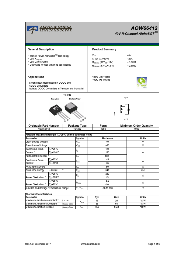
| Description | N-Channel MOSFET |
|
|
The value of RθJA is measured with the device mounted on 1in2 FR-4 board with 2oz. Copper, in a still air environment with TA =25°C. The Power dissipation PDSM is based on R θJA t≤ 10s.
| Brand Logo | Part Number | Description | Other Manufacturers |
|---|---|---|---|
| AOW66412 | N-Channel MOSFET | INCHANGE |
View all Alpha & Omega Semiconductors datasheets
| Part Number | Description |
|---|---|
| AOW66616 | 60V N-Channel MOSFET |
| AOW10N60 | 10A N-Channel MOSFET |
| AOW10N65 | 10A N-Channel MOSFET |
| AOW10T60 | 10A N-Channel MOSFET |
| AOW11N60 | 11A N-Channel MOSFET |
| AOW11S60 | Power Transistor |
| AOW11S65 | Power Transistor |
| AOW125A60 | N-Channel Power Transistor |
| AOW12N50 | 12A N-Channel MOSFET |
| AOW12N60 | 12A N-Channel MOSFET |