MSA-1120 Overview
Key Specifications
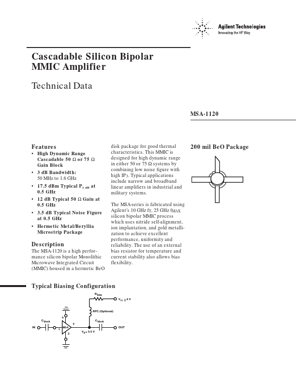
Package: SMD/SMT
Mount Type: Surface Mount
Pins: 4
Operating Voltage: 5.5 V
Description
The MSA-1120 is a high performance silicon bipolar Monolithic Microwave Integrated Circuit (MMIC) housed in a hermetic BeO Typical Biasing Configuration R bias VCC > 8 V RFC (Optional) 4 C block 3 IN 1 MSA C block OUT Vd = 5.5 V 2 2 MSA-1120 Parameter Device Current Power Dissipation[2,3] RF Input Power Junction Temperature Storage Temperature Absolute Maximum[1] 100 mA 650 mW +13 dBm 200°C –65 to 200°C Notes: 1. Permanent damage may occur if any of these limits are exceeded.
Key Features
- High Dynamic Range Cascadable 50 Ω or 75 Ω Gain Block
- 3 dB Bandwidth: 50 MHz to 1.6 GHz
- 17.5 dBm Typical P1 dB at 0.5 GHz
- 12 dB Typical 50 Ω Gain at 0.5 GHz
- 3.5 dB Typical Noise Figure at 0.5 GHz