Datasheet4U Logo Datasheet4U.com

IXFT120N15P - Polar MOSFETs

Download the IXFT120N15P datasheet PDF (IXFH120N15P included). The manufacturer datasheet provides complete specifications, pinout details, electrical characteristics, and typical applications for polar mosfets.

Features

  • z z z Symbol Test Conditions (TJ = 25°C, unless otherwise specified) VDSS VGS(th) IGSS IDSS RDS(on) VGS = 0 V, ID = 250 µA VDS = VGS, ID = 4mA VGS = ±30 VDC, VDS = 0 VDS = VDSS VGS = 0 V TJ = 175°C Characteristic Values Min. Typ. Max. 300 3.0 5.0 ±100 25 1000 17 V V nA µA µA mΩ z International standard packages Unclamped Inductive Switching (UIS) rated Low package inductance - easy to drive and to protect Fast intrinsic diode Advantages z z z Easy to mount Space savings High power density.

📥 Download Datasheet

Note: The manufacturer provides a single datasheet file (IXFH120N15P_IXYSCorporation.pdf) that lists specifications for multiple related part numbers.
Other Datasheets by IXYS Corporation

Full PDF Text Transcription

Click to expand full text
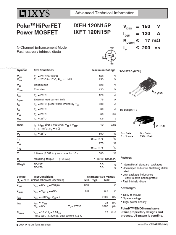
Advanced Technical Information PolarTM HiPerFET Power MOSFET N-Channel Enhancement Mode Fast recovery intrinsic diode IXFH 120N15P IXFT 120N15P VDSS = 150 V ID25 = 120 A RDS(on) ≤ 17 mΩ ≤ 200 ns trr www.DataSheet4U.com Symbol VDSS VDGR VGS VGSM ID25 Test Conditions TJ = 25°C to 175°C TJ = 25°C to 10°C; RGS = 1 MΩ Continuous Transient TC = 25°C External lead current limit TC = 25°C, pulse width limited by TJM TC = 25°C TC = 25°C TC = 25°C IS ≤ IDM, di/dt ≤ 100 A/µs, VDD ≤ VDSS, TJ ≤ 175°C, RG = 4 Ω TC = 25°C Maximum Ratings 150 150 ± 20 ± 30 120 75 300 60 50 1.5 10 600 -55 ... +175 175 -55 ...
Published: |