Click to expand full text
19-1557; Rev 0; 10/99
+2.7V to +5.5V, Low-Power, Quad, Parallel 8-Bit DAC with Rail-to-Rail Voltage Outputs
General Description
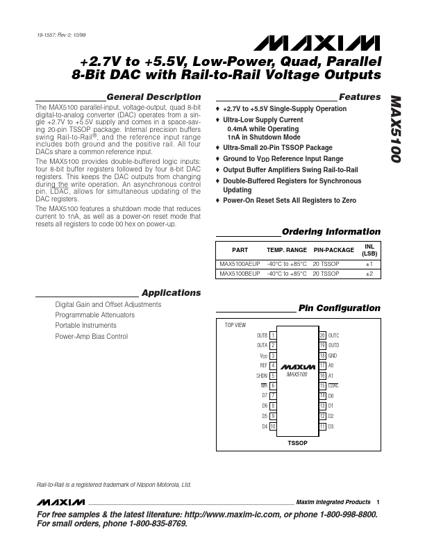
The MAX5100 parallel-input, voltage-output, quad 8-bit digital-to-analog converter (DAC) operates from a single +2.7V to +5.5V supply and comes in a space-saving 20-pin TSSOP package. Internal precision buffers swing Rail-to-Rail ® , and the reference input range includes both ground and the positive rail. All four DACs share a common reference input. The MAX5100 provides double-buffered logic inputs: four 8-bit buffer registers followed by four 8-bit DAC registers. This keeps the DAC outputs from changing during the write operation. An asynchronous control pin, LDAC , allows for simultaneous updating of the DAC registers.
 MAX5100 Datasheet