Overview
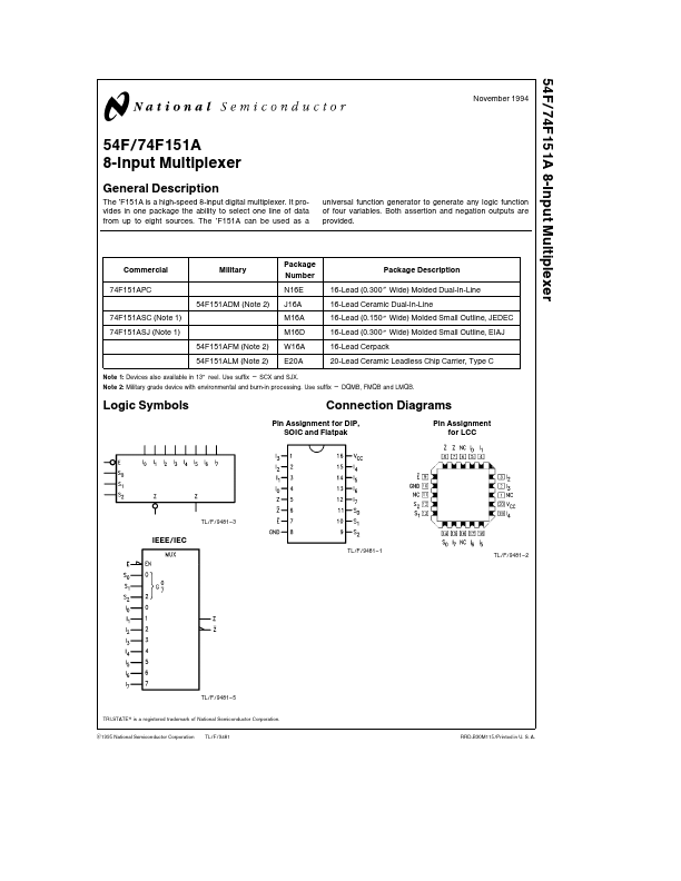
The ’F151A is a high-speed 8-input digital multiplexer It provides in one package the ability to select one line of data from up to eight sources The ’F151A can be used as a universal function generator to generate any logic function of four variables Both assertion and negation outputs are provided Commercial 74F151APC 74F151ASC (Note 1) 74F151ASJ (Note 1) Military 54F151ADM (Note 2) 54F151AFM (Note 2) 54F151ALM (Note 2) Package Number N16E J16A M16A M16D W16A E20A Package Description 16-Lead (0 300 Wide) Molded Dual-In-Line 16-Lead Ceramic Dual-In-Line 16-Lead (0 150 Wide) Molded Small Outline JEDEC 16-Lead (0 300 Wide) Molded Small Outline EIAJ 16-Lead Cerpack 20-Lead Ceramic Leadless Chip Carrier Type C Note 1 Devices also available in 13 reel Use suffix e SCX and SJX Note 2 Military grade device with environmental and burn-in processing Use suffix e DQMB FMQB and LMQB Lo.