Datasheet Details
| Part number | MN6474A |
|---|---|
| Manufacturer | Panasonic |
| File Size | 115.91 KB |
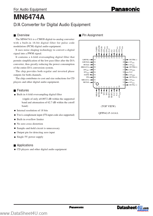
| Description | D/A Converter for Digital Audio Equipment |
| Datasheet |
 MN6474A Datasheet MN6474A Datasheet
|
|
|
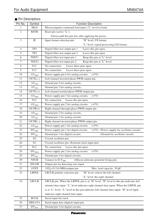
Pin No.
1 2 3 4 5 6 7 8 9 10 11 12 13 14 15 16 17 18 19 20 21 22 23 24 25 26 27 28 29 30 31 32 33 34 Symbol MLD RSTB IE TP1 TP2 TEST1 TEST2 N.C.
N.C.
) AV SS4 AV SS3 OUTL(+) AV DD3 N.C.
) AV DD1 DV DD1 DV SS1 X2 X1 N.C.
| Part number | MN6474A |
|---|---|
| Manufacturer | Panasonic |
| File Size | 115.91 KB |
| Description | D/A Converter for Digital Audio Equipment |
| Datasheet |
MN6474A Datasheet
|
|
|
|
| Part Number | Description | Manufacturer |
|---|---|---|
| MN6471 | 18-Bit D/A Converter | ETC |
| MN6472 | D/A Converter | ETC |
| MN6400 | 16-bit Self-Calibrating Sampling A/D Converter | Micro Networks |
| MN6450 | SELF-CALIBRATING SAMPLING A/D CONVERTER | Micro Networks |
| MN6025A | Microcomputer and Peripheral LSI | Matsushita Electric |
| Part Number | Description |
|---|---|
| MN6475A | D/A Converter for Digital Audio Equipment |
| MN6460A | A/D Converter for Digital Audio Equipment |
| MN61113 | 2K-Bit EEPROMs |
| MN6152U | PLL LSI with Built-In Prescaler |
| MN6153UC | PLL LSI with Built-In Prescaler |
The following content is an automatically extracted verbatim text from the original manufacturer datasheet and is provided for reference purposes only.