PI6CV857B Overview
Key Specifications
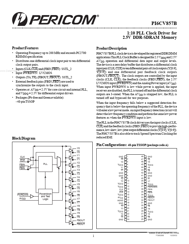
Package: TSSOP
Mount Type: Surface Mount
Pins: 48
Operating Voltage: 2.5 V
Key Features
- Operating Frequency up to 200 MHz and exceeds PC2700 RDIMM specification
- Distributes one differential clock input pair to ten differential clock output pairs
- Inputs (CLK,CLK) and (FBIN,FBIN): SSTL_2
- Input PWRDWN: LVCMOS
- Outputs (Yx, Yx), (FBOUT, FBOUT): SSTL_2