STGB20N45LZAG Description
This application-specific IGBT utilizes the most advanced PowerMESH technology optimized for coil driving in the harsh environment of automotive ignition systems. These devices show very low on-state voltage and very high SCIS energy capability over a wide operating temperature range. Moreover, ESD-protected logic level gate input and an integrated gate resistor means no external protection circuitry is required.
STGB20N45LZAG Key Features
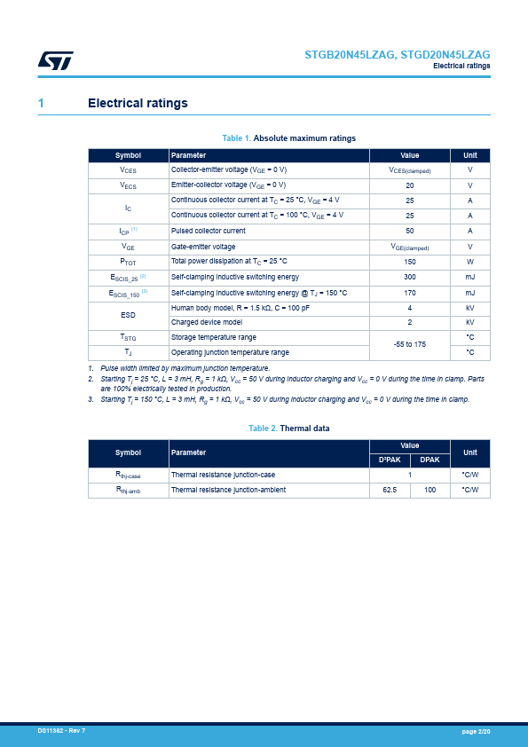
- AEC-Q101 qualified
- SCIS energy of 300 mJ @ TJ = 25 °C
- Parts are 100% tested in SCIS
- ESD gate-emitter protection
- Gate-collector high voltage clamping
- Logic level gate drive
- Very low saturation voltage
- High pulsed current capability
- Gate and gate-emitter resistor