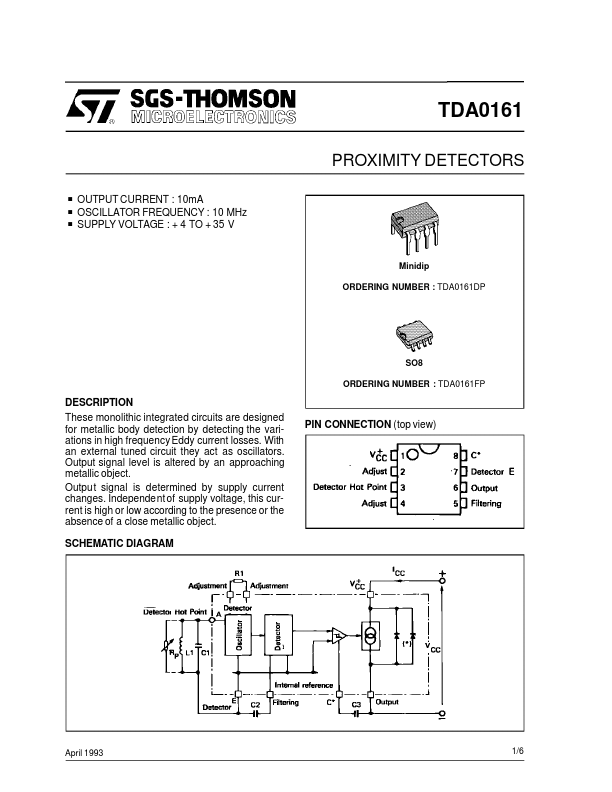
• Part: TDA0161
  • Description: PROXIMITY DETECTORS
  • Manufacturer: STMicroelectronics
  • Size: 125.30 KB
Download TDA0161 Datasheet PDF
STMicroelectronics
TDA0161
TDA0161 is PROXIMITY DETECTORS manufactured by STMicroelectronics.
DESCRIPTION These monolithic integrated circuits are designed for metallic body detection by detecting the variations in high frequency Eddy current losses. With an external tuned circuit they act as oscillators. Output signal level is altered by an approaching metallic object. Output signal is determined by supply current changes. Independent of supply voltage, this current is high or low according to the presence or the absence of a close metallic object. SCHEMATIC DIAGRAM PIN CONNECTION (top view) April 1993 1/6 ABSOLUTE MAXIMUM RATINGS Symbol VCC Tj Tstg Parameter Supply Voltage Junction Temperature Storage Temperature Range Value 35 +150 - 55 to +150 Unit V o C o C ELECTRICAL CHARACTERISTICS TDA0161DP -40o C < Tamb < +100o C TDA0161FP -40o C < Tamb < +100o C Ptot < 150m W, unless otherwise specified Symbol VCC ICC ICC Parameter Supply Voltage Reverse Voltage Limitation (ICC = -100 m A) TDA0161 Supply Current, Close Target (Tamb = +25o C) TDA0161 +4V < VCC < +35V Supply Current, Remote Target TDA0161 +4V < VCC < +35V Supply Current Transition Time C3 = 0 C3 ≠ 0 Oscillator Tuning Frequency Output Frequency (C3 = 0) Output Current Ripple - C3 = 0, C2 (p F) > 150/fosc (MHz) Negative Resistance on Terminals A and E 4kΩ < R1 < 50kΩ, fosc< 3 MHz Hysteresis at Detection Point C2 (Pf) > 150/fosc (MHz) Min. 4 Typ. 1 8 10 12 m A 1 1 (100 x C3 (n F)) 0 10 10 20 R1 1.1 R1 5 µs MHz k Hz µA Max. 35 Unit V V m A fosc f O ∆ICC Rn Hyst 0.9 R1 0.5 % - If the circuit is used at a frequency higher than 3MHz, it is remended to connect a capacitor of 100p F between terminals E and D. OPERATING MODE Between terminals A and E, the integrated circuit acts like a negative resistance equal to the external resistor R1 connected between terminals B and H. The oscillation stops when loss resistance Rp of tuned circuit bees smaller than R1. Then, the supply current will be ICC = 10m A (pins G and D). The oscillation sustains when loss resistance Rp of tuned circuit bees higher than R1....