1. Description
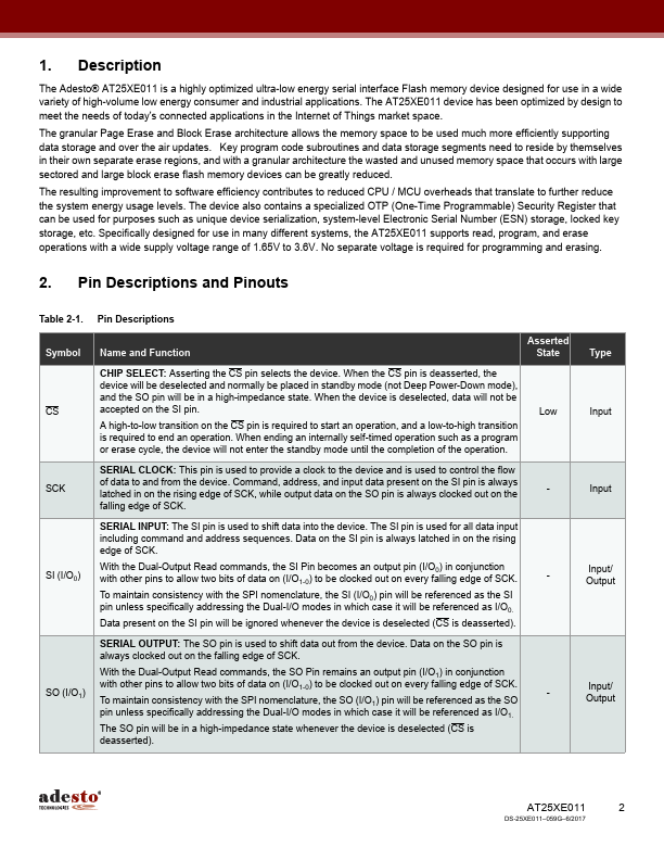
The Adesto® AT25XE011 is a highly optimized ultra-low energy serial interface Flash memory device designed for use in a wide
variety of high-volume low energy consumer and industrial applications. The AT25XE011 device has been optimized by design to
meet the needs of today's connected applications in the Internet of Things market space.
The granular Page Erase and Block Erase architecture allows the memory space to be used much more efficiently supporting
data storage and over the air updates. Key program code subroutines and data storage segments need to reside by themselves
in their own separate erase regions, and with a granular architecture the wasted and unused memory space that occurs with large
sectored and large block erase flash memory devices can be greatly reduced.
The resulting improvement to software efficiency contributes to reduced CPU / MCU overheads that translate to further reduce
the system energy usage levels. The device also contains a specialized OTP (One-Time Programmable) Security Register that
can be used for purposes such as unique device serialization, system-level Electronic Serial Number (ESN) storage, locked key
storage, etc. Specifically designed for use in many different systems, the AT25XE011 supports read, program, and erase
operations with a wide supply voltage range of 1.65V to 3.6V. No separate voltage is required for programming and erasing.
2. Pin Descriptions and Pinouts
Table 2-1. Pin Descriptions
Symbol Name and Function
Asserted
State
CHIP SELECT: Asserting the CS pin selects the device. When the CS pin is deasserted, the
device will be deselected and normally be placed in standby mode (not Deep Power-Down mode),
and the SO pin will be in a high-impedance state. When the device is deselected, data will not be
CS accepted on the SI pin.
Low
A high-to-low transition on the CS pin is required to start an operation, and a low-to-high transition
is required to end an operation. When ending an internally self-timed operation such as a program
or erase cycle, the device will not enter the standby mode until the completion of the operation.
SCK
SERIAL CLOCK: This pin is used to provide a clock to the device and is used to control the flow
of data to and from the device. Command, address, and input data present on the SI pin is always
latched in on the rising edge of SCK, while output data on the SO pin is always clocked out on the
falling edge of SCK.
-
SI (I/O0)
SERIAL INPUT: The SI pin is used to shift data into the device. The SI pin is used for all data input
including command and address sequences. Data on the SI pin is always latched in on the rising
edge of SCK.
With the Dual-Output Read commands, the SI Pin becomes an output pin (I/O0) in conjunction
with other pins to allow two bits of data on (I/O1-0) to be clocked out on every falling edge of SCK.
To maintain consistency with the SPI nomenclature, the SI (I/O0) pin will be referenced as the SI
pin unless specifically addressing the Dual-I/O modes in which case it will be referenced as I/O0.
Data present on the SI pin will be ignored whenever the device is deselected (CS is deasserted).
-
SO (I/O1)
SERIAL OUTPUT: The SO pin is used to shift data out from the device. Data on the SO pin is
always clocked out on the falling edge of SCK.
With the Dual-Output Read commands, the SO Pin remains an output pin (I/O1) in conjunction
with other pins to allow two bits of data on (I/O1-0) to be clocked out on every falling edge of SCK.
To maintain consistency with the SPI nomenclature, the SO (I/O1) pin will be referenced as the SO
pin unless specifically addressing the Dual-I/O modes in which case it will be referenced as I/O1.
The SO pin will be in a high-impedance state whenever the device is deselected (CS is
deasserted).
-
Type
Input
Input
Input/
Output
Input/
Output
AT25XE011
DS-25XE011–059G–6/2017
2