Description
/ block diagram
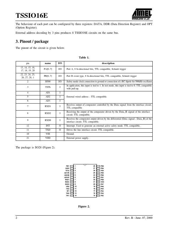
The block diagram given below shows the organization of the circuit as two blocks: the VAN controller (block 1), and the groups of specific functions (block 2) relative to the TSSIO16E.These are based on management of 16 inputs-outputs grouped together to form two 8-bit bi-directional programmable ports: port A and port B.The circuit thus ensures double exchange of information with the VAN bus (via the line interface) on the one hand and the active environment on the other.htt
Features
- q q q q q q q q q q q q
Management of 16 inputs-outputs (16-bit or two 8-bit configurable ports) VAN protocol V4.0 3 external wired address Safety mode in case of transmission loss Automatic adaptation to speed of bus from 8kTS/s to 250kTS/s CMOS 0,5µm, IO CMOS TTL compatible Internal power-on-reset Internal ring oscillator from 10 to 40MHz (for internal clock) 500kHz oscillator with external RC network (for safety mode clock usage) Supply voltage 5V±10% Typical power consomption 4mA SO28 packa.