Datasheet Details
| Part number | MC1372 |
|---|---|
| Manufacturer | Motorola |
| File Size | 318.30 KB |
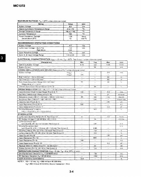
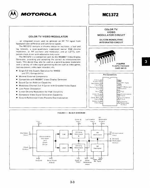
| Description | Color TV Video Modulator |
| Datasheet |
 MC1372-Motorola.pdf MC1372-Motorola.pdf
|
|
|
The MC1372 by Motorola is a Color TV Video Modulator. Below is the official datasheet preview.
| Part number | MC1372 |
|---|---|
| Manufacturer | Motorola |
| File Size | 318.30 KB |
| Description | Color TV Video Modulator |
| Datasheet |
MC1372-Motorola.pdf
|
|
|
|
Pin 1 - Clock Output Provides a rectangular ptJise output waveform with frequency equal to the chrominance subcarrier oscillalor.
📁 MC1372 Similar Datasheet