Datasheet4U Logo Datasheet4U.com

DS90CR217

+3.3V Rising Edge Data Strobe LVDS

DS90CR217 Features

* n 20 to 75 MHz shift clock support n 50% duty cycle on receiver output clock n Best

* in

* Class Set & Hold Times on TxINPUTs and RxOUTPUTs n Low power consumption n Tx + Rx Power-down mode < 400µW (max) n ± 1V common mode range (around +1.2V) n Narrow bus reduces cable size and cost n U

DS90CR217 General Description

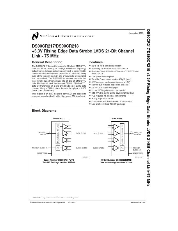
The DS90CR217 transmitter converts 21 bits of CMOS/TTL data into three LVDS (Low Voltage Differential Signaling) data streams. A phase-locked transmit clock is transmitted in parallel with the data streams over a fourth LVDS link. Every cycle of the transmit clock 21 bits of input data are sampled a.

DS90CR217 Datasheet (281.49 KB)

Preview of DS90CR217 PDF

Datasheet Details

Part number:

DS90CR217

Manufacturer:

National Semiconductor

File Size:

281.49 KB

Description:

+3.3v rising edge data strobe lvds.
DS90CR217/DS90CR218 +3.3V Rising Edge Data Strobe LVDS 21-Bit Channel Link-75 MHz November 1999 DS90CR217/DS90CR218 +3.3V Rising Edge Data Strobe LV.

📁 Related Datasheet

DS90CR211 21-Bit Channel Link (National Semiconductor)

DS90CR212 21-Bit Channel Link (National Semiconductor)

DS90CR213 21-Bit Channel Link (National Semiconductor)

DS90CR214 21-Bit Channel Link 66 MHz (National Semiconductor)

DS90CR215 +3.3V Rising Edge Data Strobe LVDS (Texas Instruments)

DS90CR215 +3.3V Rising Edge Data Strobe LVDS (National Semiconductor)

DS90CR216 +3.3V Rising Edge Data Strobe LVDS (Texas Instruments)

DS90CR216 +3.3V Rising Edge Data Strobe LVDS (National Semiconductor)

DS90CR216A 3.3-V Rising Edge Data Strobe LVDS Receiver (Texas Instruments)

DS90CR216A-Q1 3.3-V Rising Edge Data Strobe LVDS Receiver (Texas Instruments)

TAGS

DS90CR217 +3.3V Rising Edge Data Strobe LVDS National Semiconductor

Image Gallery

DS90CR217 Datasheet Preview Page 2 DS90CR217 Datasheet Preview Page 3

DS90CR217 Distributor