GP800FSM18
GP800FSM18 is Hi-Reliability Single Switch IGBT Module manufactured by Dynex Semiconductor.
FEATURES s s s s
High Thermal Cycling Capability 800A Per Module Non Punch Through Silicon Isolated MMC Base with Al N Substrates
KEY PARAMETERS VCES (typ) VCE(sat) (max) IC (max) IC(PK)
1800V 3.5V 800A 1600A
APPLICATIONS s s s s
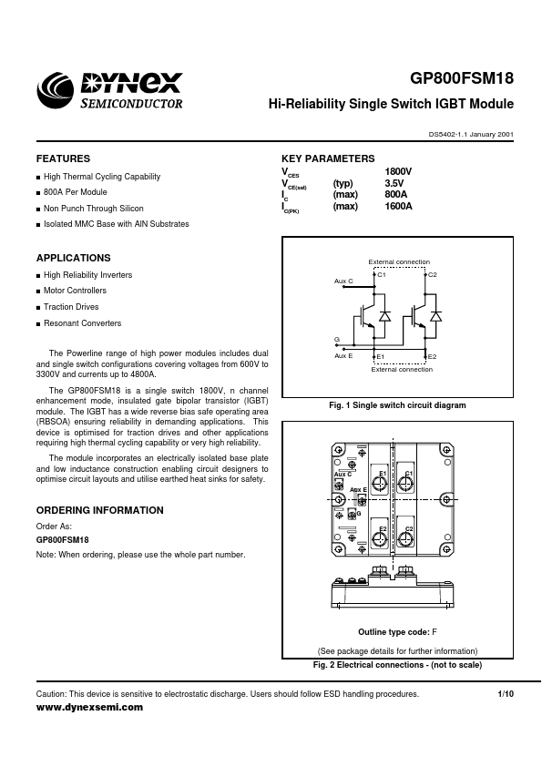
External connection C1 Aux C C2
High Reliability Inverters Motor Controllers Traction Drives Resonant Converters
The Powerline range of high power modules includes dual and single switch configurations covering voltages from 600V to 3300V and currents up to 4800A. The GP800FSM18 is a single switch 1800V, n channel enhancement mode, insulated gate bipolar transistor (IGBT) module. The IGBT has a wide reverse bias safe operating area (RBSOA) ensuring reliability in demanding applications. This device is optimised for traction drives and other applications requiring high thermal cycling capability or very high reliability. The module incorporates an electrically isolated base plate and low inductance construction enabling circuit designers to optimise circuit layouts and utilise earthed heat sinks for safety.
Aux E
E1
E2
External connection
Fig. 1 Single switch circuit diagram
Aux C Aux E
E1
C1
ORDERING INFORMATION
Order As: GP800FSM18 Note: When ordering, please use the whole part number.
G E2 C2
Outline type code: F (See package details for further information) Fig. 2 Electrical connections
- (not to scale)
Caution: This device is sensitive to electrostatic discharge. Users should follow ESD handling procedures.
1/10
.dynexsemi.
ABSOLUTE MAXIMUM RATINGS
Stresses above those listed under 'Absolute Maximum Ratings' may cause permanent damage to the device. In extreme conditions, as with all semiconductors, this may include potentially hazardous rupture of the package. Appropriate safety precautions should always be followed. Exposure to Absolute Maximum Ratings may affect device reliability. Tcase = 25˚C unless stated otherwise Symbol VCES VGES IC IC(PK) Pmax Visol Parameter Collector-emitter voltage...