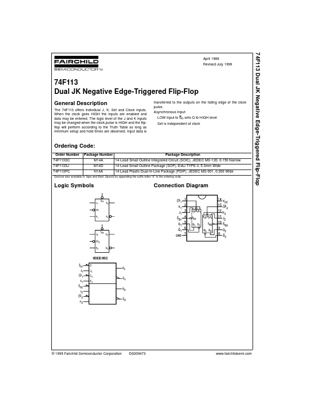
GENERAL DESCRIPTION
Input data is transferred to the outputs on the falling edge of the clock pulse. Asynchronous input: LOW input to SD sets Q to HIGH level Set is independent of clock Ordering Code: Order Number 74F113SC 74F113SJ 74F113PC Package Number M14A M14D N14A Package DESCRIPTION
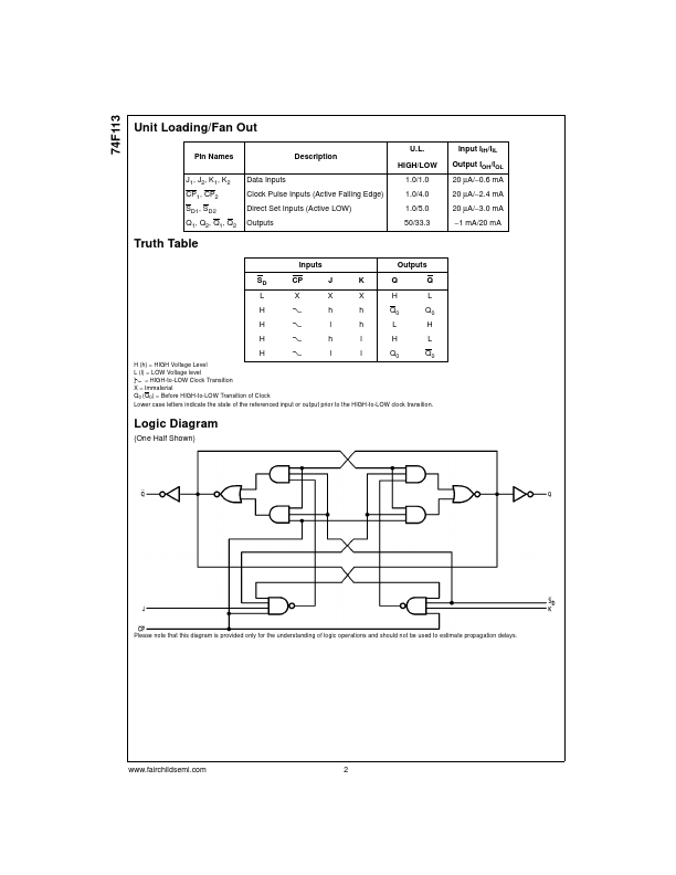
14-Lead Small Outline Integrated Circuit (SOIC), JEDEC MS-120, 0.150 Narrow 14-Lead Small Outline Package (SOP), EIAJ TYPE II, 5.3mm Wide 14-Lead Plastic Dual-In-Line Package (PDIP), JEDEC MS-001, 0.300 Wide Devices also available in Tape and Reel. Specify by appending the suffix letter “X” to the ordering code. Logic Symbols Connection Diagram IEEE/IEC © 1999 Fairchild Semiconductor Corporation DS009473 74F113 Unit Loading/Fan Out U.L. Pin Names J1, J2, K1, K2 CP1, CP2 SD1, SD2 Q1, Q2, Q1, Q2 Data Inputs Clock Pulse Inputs (Active Falling Edge) Direct Set Inputs (Active LOW) Outputs DESCRIPTION
HIGH/LOW 1.0/1.0 1.0/4.0 1.0/5.0 50/33.3 Input IIH/IIL Output IOH/IOL 20 µA/−0.6 mA 20 µA/−2.4 mA 20 µA/−3... Fairchild Semiconductor