CD4514BC
Description
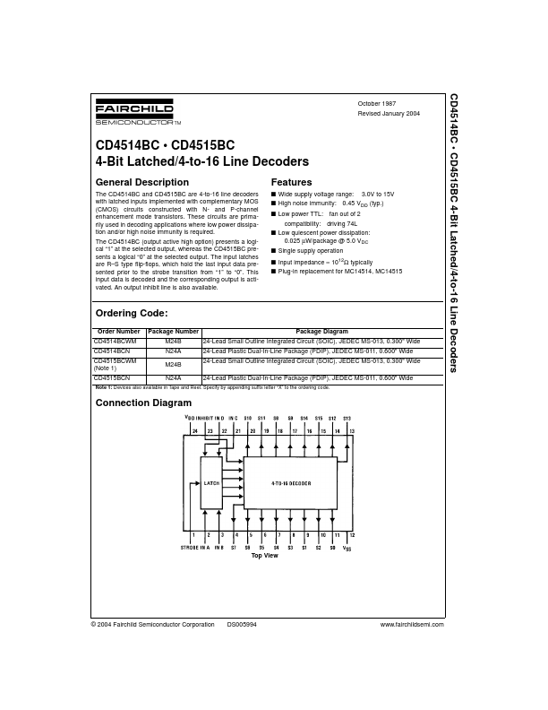
The CD4514BC and CD4515BC are 4-to-16 line decoders with latched inputs implemented with complementary MOS (CMOS) circuits constructed with N- and P-channel enhancement mode transistors. These circuits are primarily used in decoding applications where low power dissipation and/or high noise immunity is required.
Key Features
- 025 µW/package @ 5.0 VDC s Single supply operation s Input impedance = 1012Ω typically s Plug-in replacement for MC14514, MC14515 Ordering Code: Order Number Package Number Package Diagram