Datasheet4U Logo Datasheet4U.com

MRF9200LR3 - N-Channel Enhancement-Mode Lateral MOSFETs

General Description

RF Bead, Surface Mount (0603) RF Bead, Surface Mount (0805) 2.2 pF Chip Capacitor (0603) 47 pF Chip Capacitors (0805) 2.0 pF Chip Capacitor (0603) 0.4 2.5 pF Variable Capacitors 8.2 pF Chip Capacitor (0603) 0.8 8.0 pF Variable Capacitors 12 pF Chip Capacitors (0603) 10 pF Chip Capaci

Key Features

  • er 3rd Order 5th Order 7th Order VDD = 26 Vdc, Pout = 200 W (PEP), IDQ = 1800 mA Two-Tone Measurements, Center Frequency = 880 MHz 1 TWO-TONE.

📥 Download Datasheet

Full PDF Text Transcription (Reference)

The following content is an automatically extracted verbatim text from the original manufacturer datasheet and is provided for reference purposes only.

View original datasheet text
www.DataSheet4U.com Freescale Semiconductor Technical Data MRF9200L Rev. 1, 12/2004 RF Power Field Effect Transistors N−Channel Enhancement−Mode Lateral MOSFETs Designed for broadband commercial and industrial applications with frequencies to 1000 MHz. The high gain and broadband performance of these devices make them ideal for large−signal, common−source amplifier applications in 26 volt base station equipment.
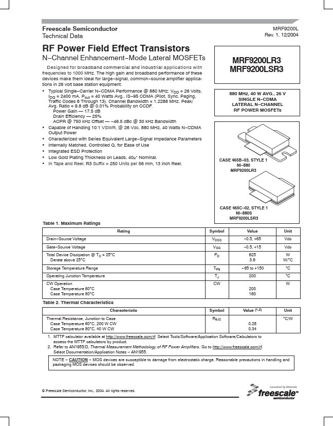
 • Typical Single−Carrier N−CDMA Performance @ 880 MHz: VDD = 26 Volts, IDQ = 2400 mA, Pout = 40 Watts Avg., IS−95 CDMA (Pilot, Sync, Paging, Traffic Codes 8 Through 13). Channel Bandwidth = 1.2288 MHz. Peak/ Avg. Ratio = 9.8 dB @ 0.01% Probability on CCDF. Power Gain — 17.5 dB Drain Efficiency — 25% ACPR @ 750 kHz Offset — −46.