Datasheet Details
| Part number | HM15N120AT |
|---|---|
| Manufacturer | H&M Semiconductor |
| File Size | 0.99 MB |
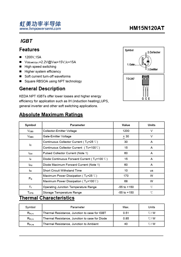
| Description | IGBT |
| Download | HM15N120AT Download (PDF) |
|
|
Overview: HM15N120AT IGBT.
| Part number | HM15N120AT |
|---|---|
| Manufacturer | H&M Semiconductor |
| File Size | 0.99 MB |
| Description | IGBT |
| Download | HM15N120AT Download (PDF) |
|
|
|
KEDA NPT IGBTs offer lower losses and higher energy efficiency for application such as IH (induction heating),UPS, general inverter and other soft switching applications.
Absolute Maximum Ratings Symbol Parameter VCES VGES Collector-Emitter Voltage Gate-Emitter Voltage Continuous Collector Current ( TC=25 ℃) IC Continuous Collector Current ( TC=100℃) ICM Pulsed Collector Current (Note 1) IF Diode Continuous Forward Current ( TC=100 ℃) IFM Diode Maximum Forward Current (Note 1) tsc Short Circuit Withstand Time Maximum Power Dissipation ( TC=25 ℃) PD Maximum Power Dissipation ( TC=100℃) TJ Operating Junction Temperature Range TSTG Storage Temperature Range Thermal Characteristics Symbol Rth j-c Rth j-c Rth j-a Parameter Thermal Resistance, Junction to case for IGBT Thermal Resistance, Junction to case for Diode Thermal Resistance, Junction to Ambient Value 1200 + 30 30 15 60 15 60 10 170 68 -55 to +150 -55 to +150 Max.
0.51 0.85 40 Units V V A A A A A us W W ℃ ℃ Units ℃/ W ℃/ W ℃/ W HM15N120AT Electrical Characteristics (TC=25℃ unless otherwise noted ) Symbol BVCES ICES IGES Parameter Collector-Emitter Breakdown Voltage Collector-Emitter Leakage Current Gate Leakage Current, Forward Gate Leakage Current, Reverse VGE(th) VCE(sat) Qg Qge Qgc Gate Threshold Voltage Collector-Emitter Saturation Voltage Total Gate Charge Gate-Emitter Charge Gate-Collector Charge t d(on) Turn-on Delay Time tr Turn-on Rise Time t d(off) Turn-off Delay Time tf Turn-off Fall Time Eon Turn-on Switching Loss Eoff Turn-off Switching Loss Ets Total Switching Loss Cies Coes Cres Input Capacitance Output Capacitance Reverse Transfer Capacitance RGint Integrated gate resistor Test Conditions VGE= 0V, IC= 250uA VCE= 1200V, VGE= 0V VGE=30V, VCE
Compare HM15N120AT distributor prices and check real-time stock availability from major suppliers. Prices and inventory may vary by region and order quantity.
| Part Number | Description |
|---|---|
| HM15N10K | N-Channel Enhancement Mode Power MOSFET |
| HM15N25F | N-channel Enhanced VDMOSFET |
| HM15N50 | 500V N-Channel MOSFET |
| HM15N50F | 500V N-Channel MOSFET |
| HM1509 | 2A 150KHz 40V Buck DC to DC Converter |
| HM150N03 | N-Channel Enhancement Mode Power MOSFET |
| HM1530 | 3A 380KHz 18V Buck DC to DC Converter |
| HM1534 | STEP-UP SWITCHING REGULATOR |
| HM1583 | 3A 380KHz 23V Buck DC to DC Converter |
| HM1588 | 2.0A 100V High Efficiency synchronous Step-Down DC/DC Converter |