IXFB100N50P
IXFB100N50P is Power MOSFET manufactured by IXYS.
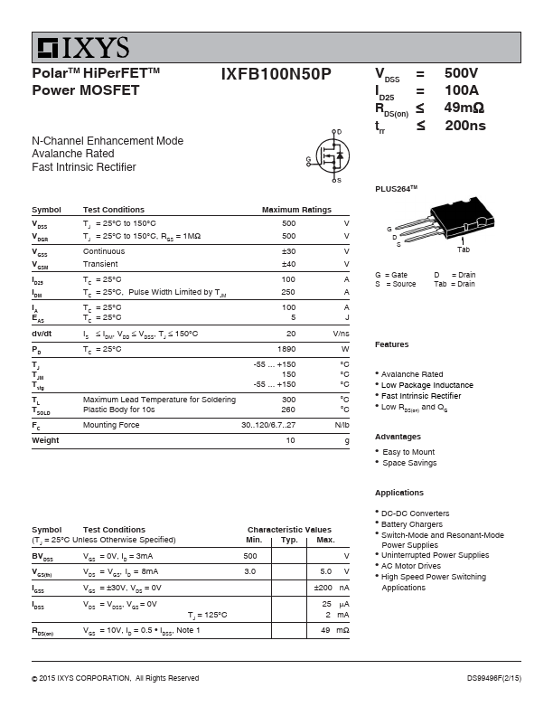
Polar HVTM Hi Per FET Power MOSFET
N-Channel Enhancement Mode Avalanche Rated Fast Intrinsic Diode
IXFB 100N50P
VDSS ID25
RDS(on) trr
= 500 V = 100 A ≤ 49 mΩ ≤ 200 ns
Symbol VDSS VDGR VGSS VGSM ID25 IDRMS IDM IAR EAR EAS dv/dt PD TJ TJM Tstg TL TSOLD FC Weight
Test Conditions TJ = 25° C to 150° C TJ = 25° C to 150° C; RGS = 1 MΩ Continuous Transient TC = 25° C External lead current limit TC = 25° C, pulse width limited by TJM TC = 25° C TC = 25° C TC = 25° C IS ≤ IDM, di/dt ≤ 100 A/µs, VDD ≤ VDSS, TJ ≤150° C, RG = 2 Ω TC = 25° C
Maximum Ratings 500 500 ±30 ±40 100 75 250 100 100 5 20 1250 -55 ... +150 150 -55 ... +150 V V V V A A A A m J J V/ns W °C °C °C °C °C N/lb g
PLUS264TM (IXFB)
(TAB) D S
G = Gate S = Source
D = Drain TAB = Drain
Features l l l l
International standard packages Fast recovery diode Unclamped Inductive Switching (UIS) rated Low package inductance
- easy to drive and to protect
1.6 mm (0.062 in.) from case for 10 s Plastic body for 10 s Mounting force
300 260 30..120/7 2.7 10
Advantages l l l
Plus 264TM package for clip or spring Space savings High power density
Symbol Test Conditions (TJ = 25° C, unless otherwise specified) BVDSS VGS(th) IGSS IDSS RDS(on) VGS = 0 V, ID = 3 m A VDS = VGS, ID = 8 m A VGS = ±30 VDC, VDS = 0 VDS = VDSS VGS = 0 V TJ = 125° C
Characteristic Values Min. Typ. Max. 500 3.0 5.0 ±200 25 2000 49 V V n A µA µA mΩ
VGS = 10 V, ID = 0.5 ID25, Note 1
..net © 2006 IXYS All rights reserved
DS99496E(01/06)
IXFB 100N50P
Symbol Test Conditions Characteristic Values (TJ = 25° C, unless otherwise specified) Min. Typ. Max. 50 80 20 VGS = 0 V, VDS = 25 V, f = 1 MHz 1700 140 36 VGS = 10 V, VDS = 0.5 VDSS, ID =0.5 ID25 RG = 1 Ω (External) 29 110 26 240 VGS = 10 V, VDS = 0.5 VDSS, ID = 0.5 ID25 96 78 S n F p F p F ns ns ns ns n C n C n C 0.10 ° C/W 0.13 ° C/W PLUS264TM (IXFB) Outline gfs Ciss Coss Crss td(on) tr td(off) tf Qg(on) Qgs Qgd Rth JC Rth CS
VDS = 20 V; ID = 0.5 ID25, Note 1
Source-Drain Diode...