Datasheet4U Logo Datasheet4U.com

IXFL30N120P - Polar HiPerFET Power MOSFET

Datasheet Summary

Features

  • z z V~ N/lb. g z FC Weight UL recognized package Silicon chip on Direct-Copper-Bond substrate - High power dissipation - Isolated mounting surface - 2500V electrical isolation Unclamped Inductive Switching (UIS) rated Low package inductance - easy to drive and to protect Fast intrinsic diode Advantages z z Symbol Test Conditions (TJ = 25°C, unless otherwise specified) BVDSS VGS(th) IGSS IDSS RDS(on) VGS = 0V, ID = 3mA VDS = VGS, ID = 1mA VGS = ± 30V, VDS = 0V VDS = VDSS VGS = 0V VGS = 10V,.

📥 Download Datasheet

Datasheet preview – IXFL30N120P

Datasheet Details

Part number IXFL30N120P
Manufacturer IXYS Corporation
File Size 129.15 KB
Description Polar HiPerFET Power MOSFET
Datasheet download datasheet IXFL30N120P Datasheet
Additional preview pages of the IXFL30N120P datasheet.
Other Datasheets by IXYS Corporation

Full PDF Text Transcription

Click to expand full text
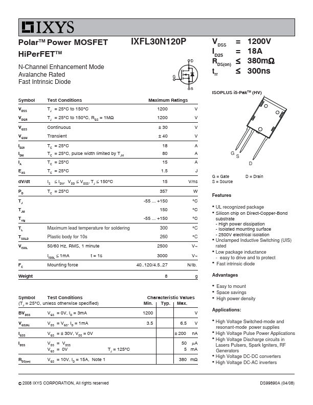
PolarTM Power MOSFET HiPerFETTM N-Channel Enhancement Mode Avalanche Rated Fast Intrinsic Diode Symbol VDSS VDGR VGSS VGSM ID25 IDM IA EAS dV/dt PD TJ TJM Tstg TL TSOLD VISOL www.DataSheet4U.net IXFL30N120P VDSS ID25 RDS(on) trr = = ≤ ≤ 1200V 18A 380mΩ 300ns ISOPLUS i5-PakTM (HV) Test Conditions TJ = 25°C to 150°C TJ = 25°C to 150°C, RGS = 1MΩ Continuous Transient TC = 25°C TC = 25°C, pulse width limited by TJM TC = 25°C TC = 25°C IS ≤ IDM, VDD ≤ VDSS, TJ ≤ 150°C TC = 25°C Maximum Ratings 1200 1200 ± 30 ± 40 18 80 15 1.5 15 357 -55 ... +150 150 -55 ... +150 Maximum lead temperature for soldering Plastic body for 10s 50/60 Hz, RMS, 1 minute IISOL ≤ 1mA Mounting force t = 1s 300 260 2500 3000 40..120/4.5..
Published: |