IXTT100N25P Description
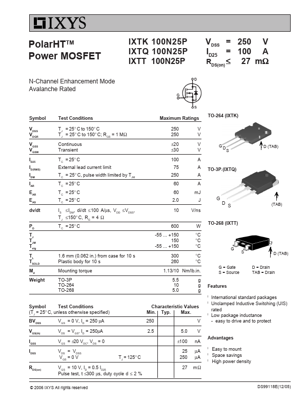
+150 °C 300 °C 260 °C 1.13/10 Nm/lb.in. 5.5 g 10 g 5.0 g Symbol Test Conditions (TJ = 25° C, unless otherwise specified) BV DSS V GS = 0 V, I D = 250 µA Characteristic Values Min.
IXTT100N25P Key Features
- easy to drive and to protect