IXTT140N10P Description
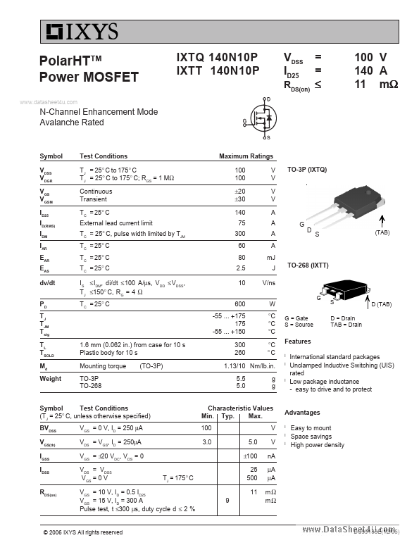
PolarHTTM Power MOSFET.
IXTT140N10P Key Features
- easy to drive and to protect
- Amperes
IXTT140N10P is Power MOSFET manufactured by IXYS.
| Part Number | Description |
|---|---|
| IXTT100N25P | N-Channel MOSFET |
| IXTT10P50 | P-Channel MOSFET |
| IXTT110N10P | N-Channel MOSFET |
| IXTT11P50 | P-Channel MOSFET |
| IXTT1N100 | High-Voltage MOSFET |
PolarHTTM Power MOSFET.