IXGQ85N33PCD1
IXGQ85N33PCD1 is High Speed IGBT manufactured by IXYS.
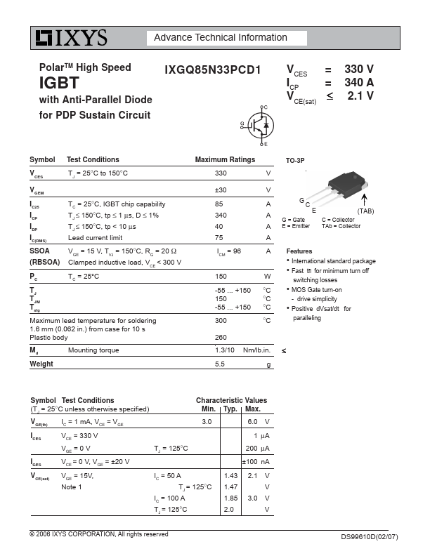
Features
- International standard package
- Fast tfi for minimum turn off switching losses
- MOS Gate turn-on
- drive simplicity
- Positive d Vsat/dt for paralleling
260 1.3/10 5.5
Nm/lb.in. g
≤
Symbol Test Conditions (TJ = 25°C unless otherwise specified)
Characteristic Values Min. Typ. Max.
V GE(th)
IC = 1 m A, VCE = VGE
3.0 6.0 V
ICES VCE = 330 V VGE = 0 V
TJ = 125°C
1 μA 200 μA
IGES VCE = 0 V, VGE = ±20 V
±100 n A
VCE(sat)
VGE = 15V, Note 1
IC = 50 A TJ = 125°C
IC = 100 A TJ = 125°C
1.43 2.1 V 1.47 V 1.85 3.0 V 2.0 V
© 2006 IXYS CORPORATION, All rights reserved
DS99610D(02/07)
Symbol Test Conditions
Characteristic Values
(TJ = 25°C unless otherwise specified)
Min. Typ. Max. gfs IC = 43 A, VCE = 10 V
30 49
Cies Coes Cres
Qg Qge Q gc
VCE = 25 V, VGE = 0 V, f = 1 MHz IC = 43 A, VGE = 15 V, VCE = 0.5 VCES
2200 155 25
80 15 23 p F p F p F n C n C n C td(on) t ri td(off) tfi
Resistive load, TJ = 25°C IC = 50 A, VGE = 15 V VCE = 240 V, RG = 5 Ω
20 ns 43 ns 87 ns 72 350 ns t d(on) tri td(off) tfi
Rth JC Rth...