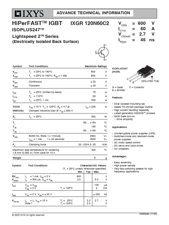
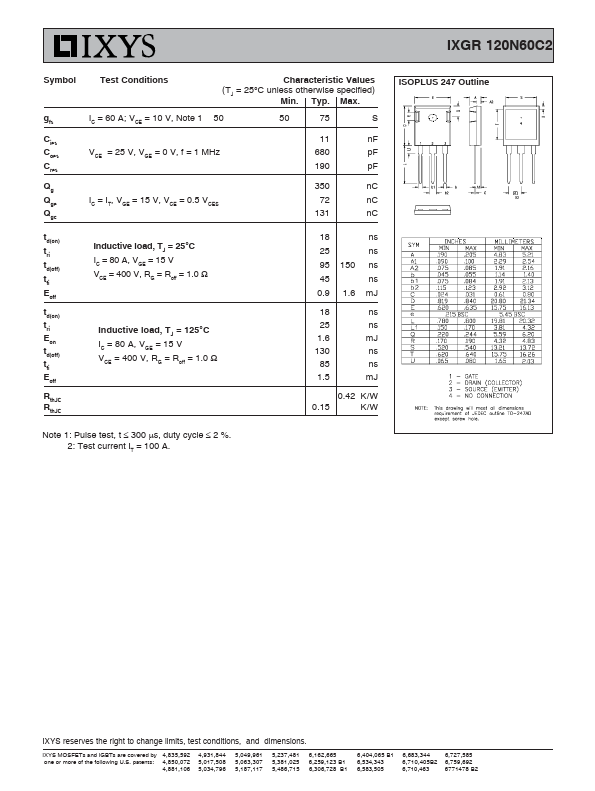
Full PDF Text Transcription for IXGR120N60C2 (Reference)
Note: Below is a high-fidelity text extraction (approx. 800 characters) for
IXGR120N60C2. For precise diagrams, and layout, please refer to the original PDF.
ADVANCE TECHNICAL INFORMATION HiPerFASTTM IGBT IXGR 120N60C2 ISOPLUS247TM Lightspeed 2TM Series (Electrically Isolated Back Surface) V= I CES = VC110 = t CE(sat) = fi(typ...
View more extracted text
ctrically Isolated Back Surface) V= I CES = VC110 = t CE(sat) = fi(typ) 600 60 2.7 45 V A V ns Symbol Test Conditions VCES VCGR VGES VGEM TJ = 25°C to 150°C TJ = 25°C to 150°C; RGE = 1 MΩ Continuous Transient IC25 TC = 25°C (limited by leads) IC110 TC = 110°C ICM TC = 25°C, 1 ms SSOA (RBSOA) VGE = 15 V, TVJ = 125°C, RG = 4.7 Ω Clamped inductive load @ VCE ≤ 600 V PC TC = 25°C TJ TJM Tstg VISOL FC 50/60 Hz, RMS, t = 1minute IISOL < 1 mA t = 20 seconds Clamping force Maximum lead temperature for soldering 1.6 mm (0.062 in.) from case for 10 s Weight Maximum Ratings 600 V 600 V ± 20 ± 30 V V 75 A 60 A 500 A ICM = 200 A 300 -5