IRF6711SPBF
IRF6711SPBF is Power MOSFET manufactured by International Rectifier.
- 96280
IRF6711SPb F IRF6711STRPb F l l l l l l l l l
Ro HS pliant and Halogen Free Low Profile (<0.7 mm) Dual Sided Cooling patible Ultra Low Package Inductance Optimized for High Frequency Switching Ideal for CPU Core DC-DC Converters Optimized for Control FET Application patible with existing Surface Mount Techniques 100% Rg tested
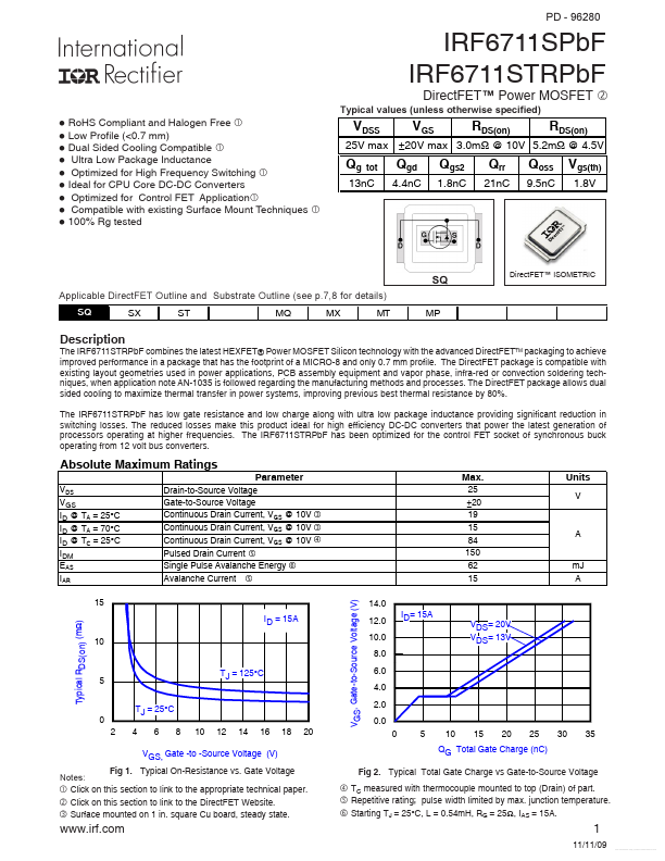
Typical values (unless otherwise specified)
Direct FET Power MOSFET RDS(on) Qgs2
1.8n C
VDSS Qg tot
VGS Qgd
4.4n C
RDS(on) Qoss
9.5n C
25V max ±20V max 3.0mΩ @ 10V 5.2mΩ @ 4.5V
Qrr
21n C
Vgs(th)
1.8V
13n C
Applicable Direct FET Outline and Substrate Outline (see p.7,8 for details)
Direct FET ISOMETRIC
Description
The IRF6711STRPb F bines the latest HEXFET® Power MOSFET Silicon technology with the advanced Direct FETTM packaging to achieve improved performance in a package that has the footprint of a MICRO-8 and only 0.7 mm profile. The Direct FET package is patible with existing layout geometries used in power applications, PCB assembly equipment and vapor phase, infra-red or convection soldering techniques, when application note AN-1035 is followed regarding the manufacturing methods and processes. The Direct FET package allows dual sided cooling to maximize thermal transfer in power systems, improving previous best thermal resistance by 80%. The IRF6711STRPb F has low gate resistance and low charge along with ultra low package inductance providing significant reduction in switching losses. The reduced losses make this product ideal for high efficiency DC-DC converters that power the latest generation of processors operating at higher frequencies. The IRF6711STRPb F has been optimized for the control FET socket of synchronous buck operating from 12 volt bus...