IRFH7085PBF
Overview
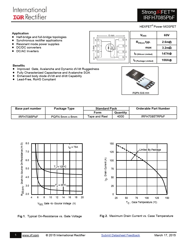
Application Half-bridge and full-bridge topologies Synchronous rectifier applications Resonant mode power supplies DC/DC converters DC/AC Inverters Benefits Improved Gate, Avalan...
| Part | IRFH7085PBF |
|---|---|
| Description | Power MOSFET |
| Category | MOSFET |
| Manufacturer | International Rectifier |
| Size | 477.68 KB |
Application Half-bridge and full-bridge topologies Synchronous rectifier applications Resonant mode power supplies DC/DC converters DC/AC Inverters Benefits Improved Gate, Avalan...
| Part Number | Manufacturer | Description |
|---|---|---|
| AP9563GH | Advanced Power Electronics Corp | P-CHANNEL ENHANCEMENT MODE POWER MOSFET |
| FCPF360N65S3R0L | onsemi | N-Channel MOSFET |
| A2SHB | HAOHAI | N-Channel MOSFET |