MMBFU310LT1 Overview
Key Features
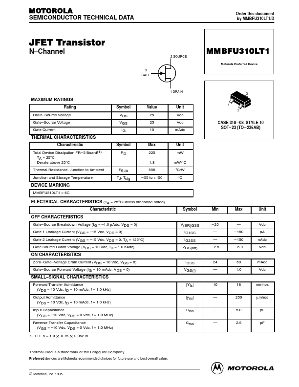
- Source Voltage Gate
- Source Voltage Gate Current Symbol VDS VGS IG Value 25 25 10 Unit Vdc Vdc mAdc CASE 318
| Part | MMBFU310LT1 |
|---|---|
| Description | JFET Transistor |
| Category | Transistor |
| Manufacturer | Motorola Semiconductor |
| Size | 161.76 KB |
| Part Number | Manufacturer | Description |
|---|---|---|
| MMBFU310LT1 | onsemi | JFET Transistor |
| MMBFU310LT1G | onsemi | N-Channel JFET Transistor |