Datasheet Summary
..
54ACT112 Dual JK Negative Edge-Triggered Flip-Flop
September 1998
54ACT112 Dual JK Negative Edge-Triggered Flip-Flop
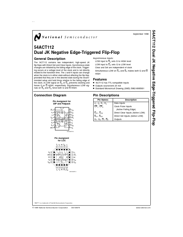
General Description
The ’ACT112 contains two independent, high-speed JK flip-flops with Direct Set and Clear inputs. Synchronous state changes are initiated by the falling edge of the clock. Triggering occurs at a voltage level of the clock and is not directly related to the transition time. The J and K inputs can change when the clock is in either state without affecting the flip-flop, provided that they are in the desired state during the remended setup and hold times relative to the falling edge of the clock. A LOW signal on SD or CD prevents...