2SB1207
Overview
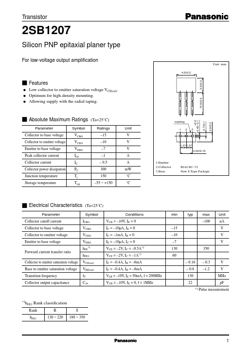
- 27 1.27 V A A mW ˚C ˚C 1:Emitter 2:Collector 3:Base
- 54±0.15 EIAJ:SC-72 New S Type Package s Electrical Characteristics Parameter Collector cutoff current Collector to base voltage Collector to emitter voltage Emitter to base voltage Forward current transfer ratio Collector to emitter saturation voltage Base to emitter saturation voltage Transition frequency Collector output capacitance (Ta=25˚C) Symbol ICBO VCBO VCEO VEBO hFE
- 1 Conditions VCB = -10V, IE = 0 IC = -10µA, IE = 0 IC = -1mA, IB = 0 IE = -10µA, IC = 0 VCE = -2V, IC = -0.5A*2 VCE = -2V, IC = -1A*2 IC = -0.4A, IB = -8mA IC = -0.4A, IB = -8mA VCB = -10V, IE = 50mA, f = 200MHz VCB = -10V, IE = 0, f = 1MHz min typ max -100
- 0±0.2 marking +0.2 0.45-0.1 s Absolute Maximum Ratings (Ta=25˚C)
- 6±0.5 Low collector to emitter saturation voltage VCE(sat). Optimum for high-density mounting. Allowing supply with the radial taping. Unit nA V V V -15 -10 -7 130 60 - 0.16 - 0.8 130 22
- 2 350 hFE2 VCE(sat) VBE(sat) fT Cob - 0.3 -1.2 V V MHz pF Pulse measurement
- 1h FE1 Rank classification R 130 ~ 220 S 180 ~ 350 Rank hFE1 1 Transistor PC - Ta 500 -1.2 Ta=25˚C 450 -1.0 IB=-10mA -9mA -8mA -7mA -6mA -5mA -4mA -3mA -2mA -1mA 2SB1207 IC - VCE -100 VBE(sat) - IC Base to emitter saturation voltage VBE(sat) (V) IC/IB=50 Collector power dissipation PC (mW) -30 -10 -3 25˚C -1 Ta=-25˚C 75˚C