APPLICATIONS
: s ELECTRONIC BALLASTS FOR FLUORESCENT LIGHTING DESCRIPTION
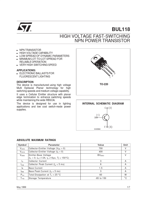
The device is designed for use in lighting applications and low cost switch-mode power supplies. TO-220 3 1 2 INTERNAL SCHEMATIC DIAGRAM ABSOLUTE MAXIMUM RATINGS
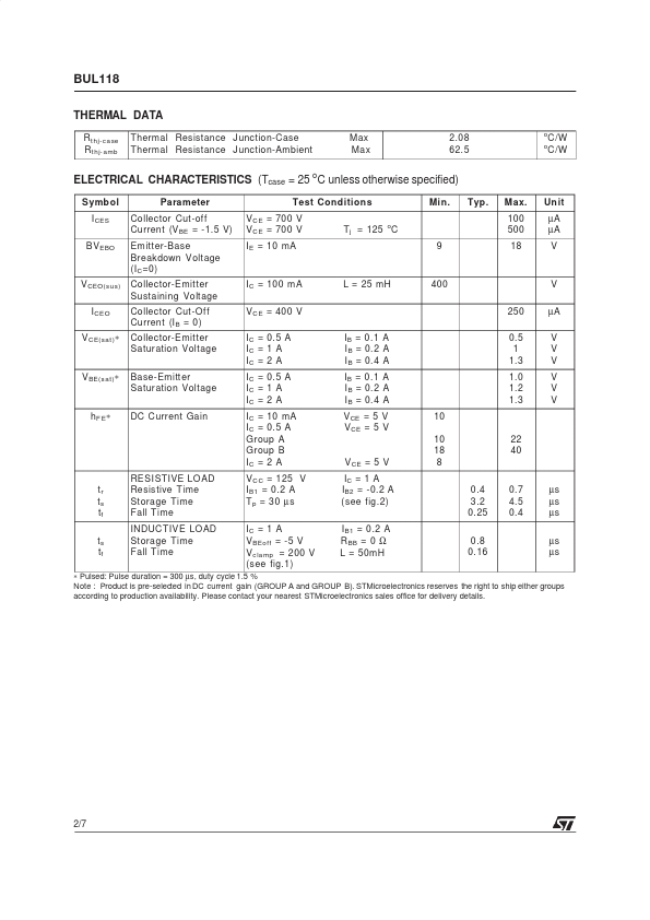
Symbol V CES V CEO V EBO IC I CM IB I BM P t ot T stg Parameter Collector-Emitter Voltage (V BE = 0) Collector-Emitter Voltage (IB = 0) Emitter-Base Voltage o (I C = 0, I B <1.5A, tp <10 µ s, Tj < 150 C) Collector Current Collector Peak Current (tp < 5 ms) Base Current Base Peak Current (tp < 5 ms) Total Dissipation at Tc = 25 C St orage Temperature o Value 700 400 BV EBO 3 6 1.5 3 60 -65 to 150 Uni t V V V A A A A W o C May 1999 1/7 BUL118 THERMAL DATA R t hj-ca se R t hj- amb Thermal Resistance Junction-Case Thermal Resistance Junction-Ambient Max Max 2.08 62.5 o o C/W C/W ELECTRICAL CHARACTERISTICS
(Tcase = 25 oC unless otherwise specified) Symb ol I CES BV EBO Parameter Collector Cut-off Current (V BE = -1.5 V) Emitter-Base Breakdown Voltage (I C =0)... STMicroelectronics