BUF620
BUF620 is Silicon NPN High Voltage Switching Transistor manufactured by Vishay.
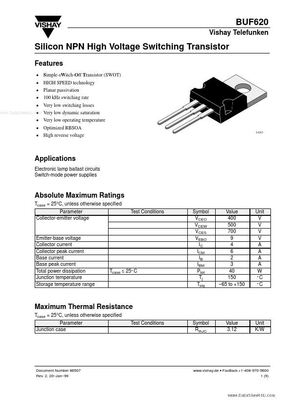
Features
D Simple-s Witch-Off Transistor (SWOT) D HIGH SPEED technology D Planar passivation D 100 k Hz switching rate D Very low switching losses
.. D
Very low dynamic saturation
D Very low operating temperature D Optimized RBSOA D High reverse voltage
Applications
Electronic lamp ballast circuits Switch-mode power supplies
Absolute Maximum Ratings
Tcase = 25°C, unless otherwise specified Parameter Collector-emitter voltage g Test Conditions Symbol VCEO VCEW VCES VEBO IC ICM IB IBM Ptot Tj Tstg Value 400 500 700 9 4 6 2 3 40 150
- 65 to +150 Unit V V V V A A A A W °C °C
Emitter-base voltage Collector current Collector peak current Base current Base peak current Total power dissipation Junction temperature Storage temperature range
Tcase ≤ 25° C
Maximum Thermal Resistance
Tcase = 25°C, unless otherwise specified Parameter Junction case Test Conditions Symbol Rth JC Value 3.12 Unit K/W
Document Number 86507 Rev. 2, 20- Jan- 99
.vishay.de
- Fax Back +1-408-970-5600 1 (9)
Vishay Telefunken Electrical Characteristics
Tcase = 25°C, unless otherwise specified Test Conditions VCE = 700 V VCE = 700 V; Tcase = 150° C Collector-emitter breakdown IC = 300 m A; L = 125 m H; voltage (figure 1) Imeasure = 100 m A Emitter-base breakdown voltage IE = 1 m A Collector-emitter saturation voltage IC = 0.6 A; IB = 0.15 A g IC = 2 A; IB = 0.7 A .. Base-emitter saturation voltage g IC = 0.6 A; IB = 0.15 A IC = 2 A; IB = 0.7 A DC forward current transfer ratio VCE = 2 V; IC = 10 m A VCE = 2 V; IC = 0.6 A VCE = 2 V; IC = 2 A VCE = 5 V; IC = 4 A Collector-emitter working voltage VS = 50 V; L = 1 m H; IC = 4 A; IB1 = 1.4 A;
- IB2 = 0.4 A;
- VBB = 5 V Dynamic y saturation voltage g IC = 2 A; IB = 0.4 A; t = 1 m s IC = 2 A; IB = 0.4 A; t = 3 m s Gain bandwidth product IC = 500 m A; VCE = 10 V; f = 1 MHz Parameter Collector cut-off current Symbol ICES ICES V(BR)CEO V(BR)EBO VCEsat VCEsat VBEsat VBEsat h FE h FE h FE h FE VCEW VCEsatdyn VCEsatdyn f T Min Typ Max 50 0.5 Unit m A m A V V V V V...