IRFIB7N50A
IRFIB7N50A is Power MOSFET manufactured by Vishay.
FEATURES
- Low Gate Charge Qg Results in Simple Drive Requirement
Available
- Improved Gate, Avalanche and Dynamic d V/dt Ro HS-
Ruggedness
PLIANT
- Fully Characterized Capacitance and Avalanche Voltage and Current
- Effective Coss Specified
- pliant to Ro HS directive 2002/95/EC
APPLICATIONS
- Switch Mode Power Supply (SMPS)
- Uninterruptible Power Supply
- High Speed Power Switching
- High Voltage Isolation = 2.5 k VRMS (t = 60 s, f = 60 Hz)
TYPICAL SMPS TOPOLOGIES
- Two Transistor Forward
- Half and Full Bridge Convertors
- Power Factor Correction Boost
ORDERING INFORMATION
Package Lead (Pb)-free
Sn Pb
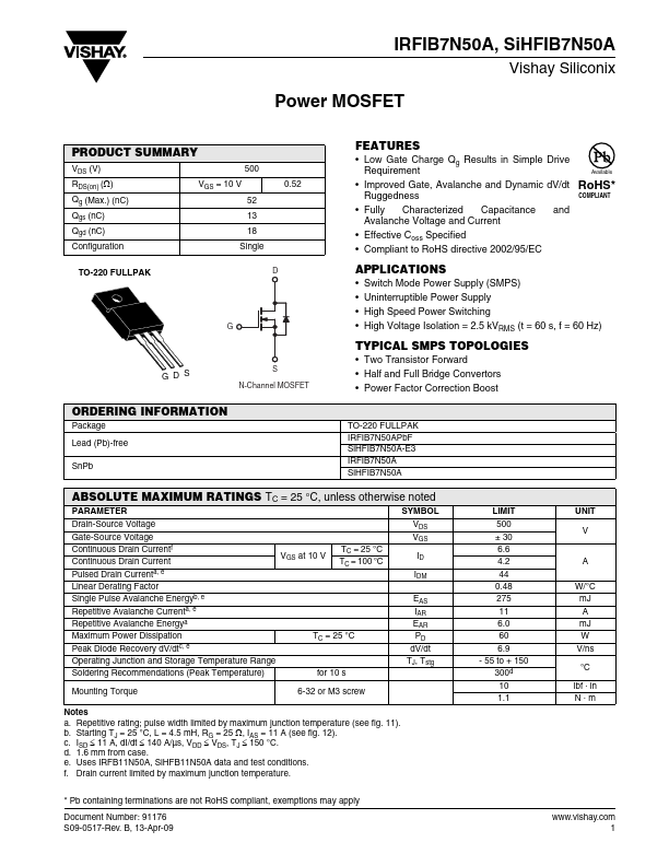
TO-220 FULLPAK IRFIB7N50APb F Si HFIB7N50A-E3 IRFIB7N50A Si HFIB7N50A
ABSOLUTE MAXIMUM RATINGS TC = 25 °C, unless otherwise noted
PARAMETER
SYMBOL
Drain-Source Voltage Gate-Source Voltage Continuous Drain Currentf Continuous Drain Current Pulsed Drain Currenta, e Linear Derating Factor Single Pulse Avalanche Energyb, e Repetitive Avalanche Currenta, e Repetitive Avalanche Energya Maximum Power Dissipation Peak Diode Recovery d V/dtc, e
VGS at 10 V
TC = 25 °C TC = 100 °C
TC = 25 °C
VDS VGS
EAS IAR EAR PD d V/dt
Operating Junction and Storage Temperature Range Soldering Remendations (Peak Temperature) for 10 s
TJ, Tstg
Mounting Torque
6-32 or M3 screw
Notes a. Repetitive rating; pulse width limited by maximum junction temperature (see fig. 11). b. Starting TJ = 25 °C, L = 4.5 m H, RG = 25 Ω, IAS = 11 A (see fig. 12). c. ISD ≤ 11 A, d I/dt ≤ 140 A/µs, VDD ≤ VDS, TJ ≤ 150 °C. d. 1.6 mm from case. e. Uses IRFB11N50A, Si HFB11N50A data and test conditions. f. Drain current limited by maximum junction temperature.
LIMIT 500 ± 30 6.6 4.2 44 0.48 275 11 6.0 60 6.9
- 55 to + 150 300d 10...