Texas Instruments 74F112
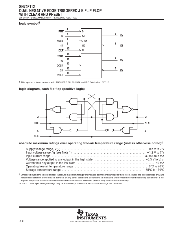
The SN74F112 contains two independent J-K negative-edge-triggered flip-flops. When PRE and CLR are inactive (high), data at the J and K inputs meeting the setup time requirements is transferred to the outputs on the negative-going edge of the clock pulse.| Part No. | 74F112 |
|---|---|
| Datasheet | 74F112 Download |
| Manufacturer |  Texas Instruments |
| Description | DUAL NEGATIVE-EDGE-TRIGGERED J-K FLIP-FLOP |
| Buy | Stock & Price |
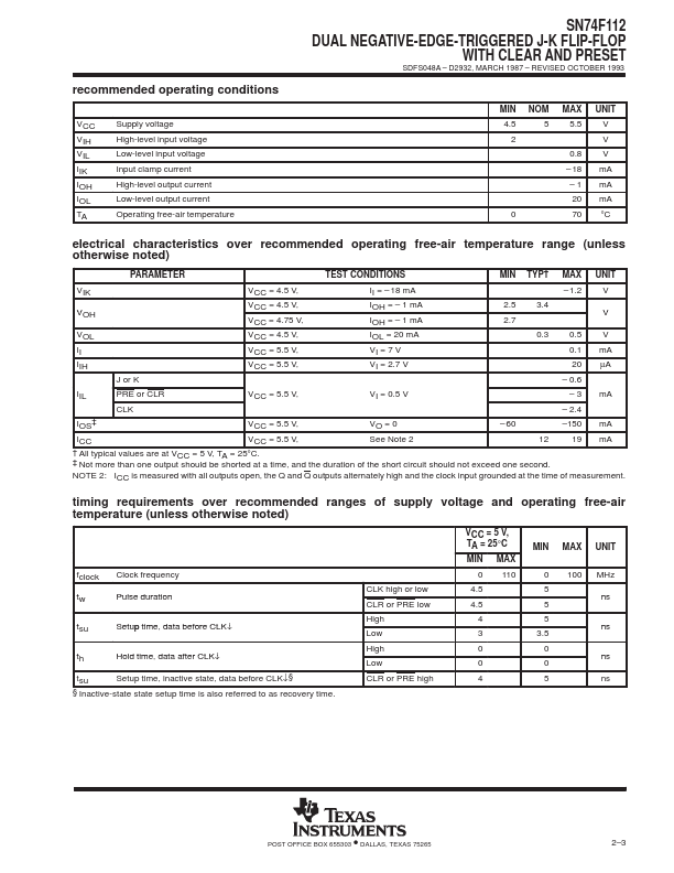
SN74F112 DUAL NEGATIVE-EDGE-TRIGGERED J-K FLIP-FLOP WITH CLEAR AND PRESET SDFS048A – D2932, MARCH 1987 – REVISED OCTOBER 1993
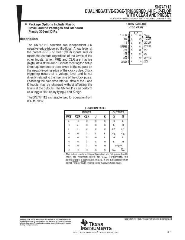
● Package Options Include Plastic Small-Outline Packages and Standard Plastic 300-mil DIPs description A low level at the preset (PRE) or clear (CLR) inputs sets or resets the outputs regardless of the levels of the other inputs. Clock triggering occurs at a voltage level and is not directly related to the rise time of the clock pulse. Following the hold-time interval, data at the J and K inputs may be changed without affecting the levels at the outputs. The SN74F112 can perform as a toggle flip-flop by tying J and K high. D OR N PACKAGE (TOP VIEW) 1CLK 1 1K 2 1J 3 1PRE 4 1Q 5 1Q 6 2Q 7 GND 8 16 VCC 15 1CLR 14 2CLR 13 2CLK 12 2K 11 2J 10 2PRE 9 2Q The SN74F112 is characterized for operation from 0°C to 70°C. FUNCTION TABLE INPUTS OUTPUTS PRE CLR CLK J K Q Q L H X X X H L H L X X X L H L L X X X H† H† H H ↓ L L Q0 Q0 H H ↓ H L H L H H ↓ L H L H H H ↓ H H Toggle H H H X X Q0 Q0 † The output levels in this configuration are not guaranteed to meet the minimum levels for VOH.
● Package Options Include Plastic Small-Outline Packages and Standard Plastic 300-mil DIPs description A low level at the preset (PRE) or clear (CLR) inputs sets or resets the outputs regardless of the levels of the other inputs. Clock triggering occurs at a voltage level and is not directly related to the rise time of the clock pulse. Following the hold-time interval, data at the J and K inputs may be changed without affecting the levels at the outputs. The SN74F112 can perform as a toggle flip-flop by tying J and K high. D OR N PACKAGE (TOP VIEW) 1CLK 1 1K 2 1J 3 1PRE 4 1Q 5 1Q 6 2Q 7 GND 8 16 VCC 15 1CLR 14 2CLR 13 2CLK 12 2K 11 2J 10 2PRE 9 2Q The SN74F112 is characterized for operation from 0°C to 70°C. FUNCTION TABLE INPUTS OUTPUTS PRE CLR CLK J K Q Q L H X X X H L H L X X X L H L L X X X H† H† H H ↓ L L Q0 Q0 H H ↓ H L H L H H ↓ L H L H H H ↓ H H Toggle H H H X X Q0 Q0 † The output levels in this configuration are not guaranteed to meet the minimum levels for VOH.