SN65MLVD082
SN65MLVD082 is 8-CHANNEL HALF-DUPLEX M-LVDS LINE TRANSCEIVERS manufactured by Texas Instruments.
- Part of the SN65MLVD080 comparator family.
- Part of the SN65MLVD080 comparator family.
FEATURES
- Low-Voltage Differential 30-Ω to 55-Ω Line Drivers and Receivers for Signaling Rates (1) Up to 250 Mbps; Clock Frequencies Up to 125 MHz
- Meets or Exceeds the M-LVDS Standard TIA/EIA-899 for Multipoint Data Interchange
- Controlled Driver Output Voltage Transition Times for Improved Signal Quality
- - 1 V to 3.4 V mon-Mode Voltage Range Allows Data Transfer With 2 V of Ground Noise
- Bus Pins High Impedance When Driver Disabled or VCC ≤ 1.5 V
- Independent Enables for each Driver
- Bus Pin ESD Protection Exceeds 8 k V
- Packaged in 64-Pin TSSOP (DGG)
- M-LVDS Bus Power Up/Down Glitch Free
APPLICATIONS
- Parallel Multipoint Data and Clock Transmission Via Backplanes and Cables
- Low-Power High-Speed Short-Reach Alternative to TIA/EIA-485
- Cellular Base Stations
- Central-Office Switches
- Network Switches and Routers
DESCRIPTION
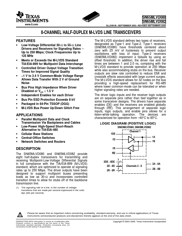
The SN65MLVD080 and SN65MLVD082 provide eight half-duplex transceivers for transmitting and receiving Multipoint-Low-Voltage Differential Signals in full pliance with the TIA/EIA-899 (M-LVDS) standard, which are optimized to operate at signaling rates up to 250 Mbps. The driver outputs have been designed to support multipoint buses presenting loads as low as 30-Ω and incorporates controlled transition times to allow for stubs off of the backbone transmission line.
(1) The signaling rate of a line, is the number of voltage transitions that are made per second expressed in the units bps (bits per second).
The M-LVDS standard defines two types of receivers, designated as Type-1 and Type-2. Type-1 receivers (SN65MLVD080) have thresholds centered about zero with 25 m V of hysteresis to prevent output oscillations with loss of input; Type-2 receivers (SN65MLVD082) implement a failsafe by using an offset threshold. In addition, the driver rise and fall times are between 1 and 2.0 ns, plying with the M-LVDS standard to provide operation at 250 Mbps while also acmodating stubs on the bus. Receiver outputs are slew rate controlled to reduce...