SN74ALVCH16821 Overview
Key Specifications
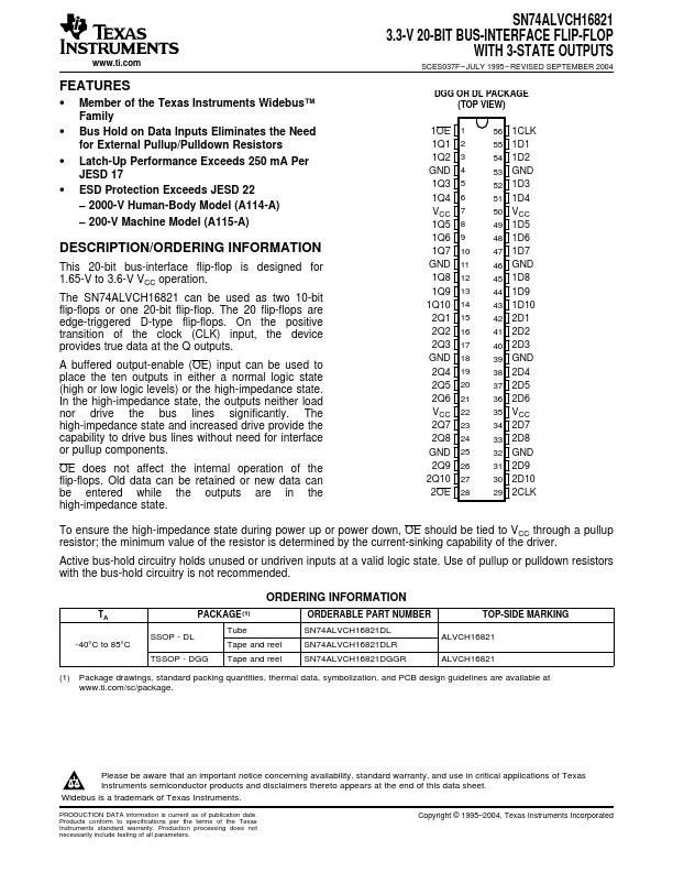
Package: TSSOP
Mount Type: Surface Mount
Pins: 56
Max Voltage (typical range): 3.6 V
Key Features
- Member of the Texas Instruments Widebus™ Family
- Bus Hold on Data Inputs Eliminates the Need for External Pullup/Pulldown Resistors
- Latch-Up Performance Exceeds 250 mA Per JESD 17
- ESD Protection Exceeds JESD 22 – 2000-V Human-Body Model (A114-A) – 200-V Machine Model (A115-A)