IXGR120N60B Key Features
- drive simplicity
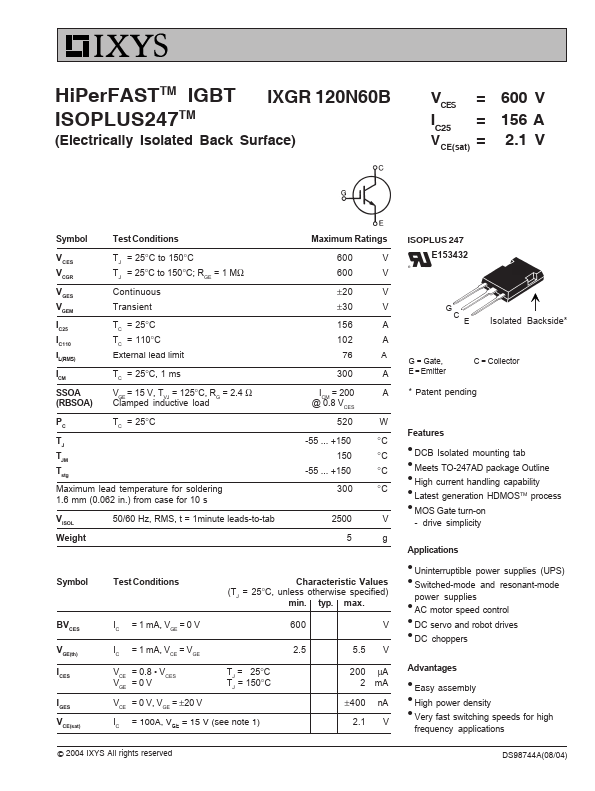
IXGR120N60B is IGBT manufactured by IXYS.
| Part Number | Description |
|---|---|
| IXGR120N60C2 | IGBT |
| IXGR16N170AH1 | High Voltage IGBT |
| IXGR24N120C3D1 | High speed PT IGBT |
| IXGR32N170AH1 | High Voltage IGBT |
| IXGR32N170H1 | High Voltage IGBT |
+150 °C 300 °C 2500 V 5 g Symbol BVCES VGE(th) ICES IGES VCE(sat) Test Conditions Characteristic Values (TJ = 25°C, unless otherwise specified) min.