IXYX100N120B3 Description
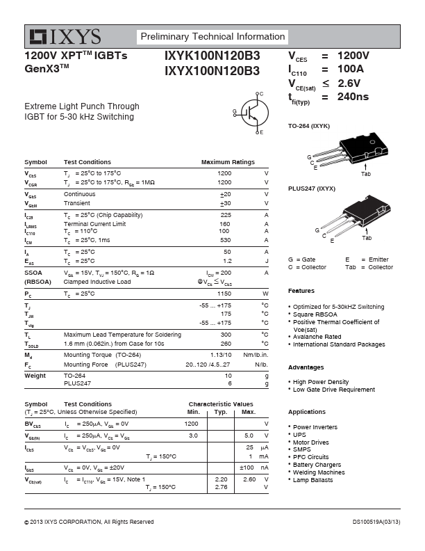
1200 V 3.0 5.0 V 25 μA 1 mA ±100 nA 2.20 2.76 2.60 V V G C E PLUS247 (IXYX) Tab G G C E Tab G = Gate C = Collector E = Emitter Tab = Collector.
IXYX100N120B3 is IGBT manufactured by IXYS.
| Part Number | Description |
|---|---|
| IXYX100N120C3 | High-Speed IGBT |
| IXYX100N65B3D1 | IGBT |
| IXYX100N65C3D1 | IGBT |
| IXYX110N120A4 | Ultra Low-Vsat PT IGBT |
| IXYX110N120B4 | 1200V IGBT |
1200 V 3.0 5.0 V 25 μA 1 mA ±100 nA 2.20 2.76 2.60 V V G C E PLUS247 (IXYX) Tab G G C E Tab G = Gate C = Collector E = Emitter Tab = Collector.