MRF21125S
Overview
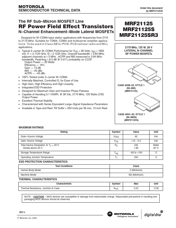
MOTOROLA SEMICONDUCTOR TECHNICAL DATA Order this document by MRF21125/D The RF Sub–Micron MOSFET Line RF Power Field Effect Transistors N–Channel Enhancement–Mode Lateral MOSFETs Designed for W–CD...
| Part | MRF21125S |
|---|---|
| Description | RF POWER FIELD EFFECT TRANSISTORS |
| Category | Transistor |
| Manufacturer | Motorola Semiconductor |
| Size | 381.28 KB |
MOTOROLA SEMICONDUCTOR TECHNICAL DATA Order this document by MRF21125/D The RF Sub–Micron MOSFET Line RF Power Field Effect Transistors N–Channel Enhancement–Mode Lateral MOSFETs Designed for W–CD...
| Part Number | Manufacturer | Description |
|---|---|---|
| MRF21125SR3 | Freescale Semiconductor | RF Power Field Effect Transistors |
| MRF21125R3 | Freescale Semiconductor | RF Power Field Effect Transistors |
| MRF21120R6 | Freescale Semiconductor | RF Power Field Effect Transistor |