- Part: MRF5S19130SR3
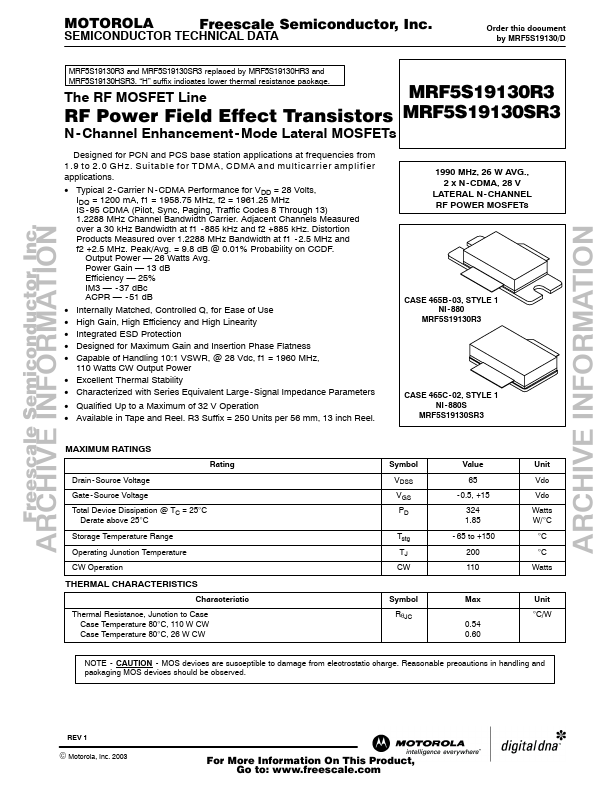
- Description: N-Channel Enhancement-Mode Lateral MOSFETs
- Manufacturer: Motorola Semiconductor
- Size: 440.44 KB
Related Motorola Semiconductor Datasheets
| Part Number | Description |
|---|---|
| MRF5S19130R3 | N-Channel Enhancement-Mode Lateral MOSFETs |
| MRF5S19100HR3 | The RF MOSFET Line RF Power Field Effect Transistors |
| MRF5S19100HSR3 | The RF MOSFET Line RF Power Field Effect Transistors |
| MRF5S19150R3 | RF Power Field Effect Transistors |
| MRF5S19150SR3 | RF Power Field Effect Transistors |