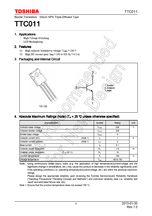
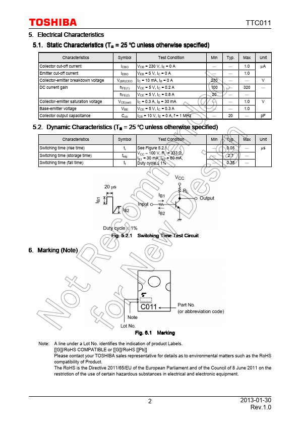
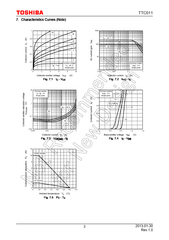
TTC011
5. Electrical Characteristics
5.1. Static Characteristics (Ta = 25 unless otherwise specified)
Characteristics
Collector cut-off current
Emitter cut-off current
Collector-emitter breakdown voltage
DC current gain
Collector-emitter saturation voltage
Base-emitter voltage
Collector output capacitance
Symbol
Test Condition
ICBO
IEBO
V(BR)CEO
hFE(1)
hFE(2)
VCE(sat)
VBE
Cob
VCB = 230 V, IE = 0 A
VEB = 5 V, IC = 0 A
IC = 10 mA, IB = 0 A
VCE = 5 V, IC = 0.2 A
VCE = 5 V, IC = 0.8 A
IC = 0.3 A, IB = 30 mA
VCE = 5 V, IC = 0.3 A
ICB = 10 V, IE = 0 A, f = 1 MHz
Min Typ. Max Unit
1.0
µA
1.0
230
V
100
320
20
1.0
V
1.0
20
pF
5.2. Dynamic Characteristics (Ta = 25 unless otherwise specified)
Characteristics
Switching time (rise time)
Switching time (storage time)
Switching time (fall time)
Symbol
Test Condition
tr
See Figure 5.2.1.
tstg
VCC ≈ 100 V, RL = 333 Ω,
IB1 = 30 mA, IB2 = 60 mA,
tf
Duty cycle ≤ 1%
Min Typ. Max Unit
0.05
µs
2.7
0.38
6. Marking (Note)
Fig. 5.2.1 Switching Time Test Circuit
Fig. 6.1 Marking
Note:
A line under a Lot No. identifies the indication of product Labels.
[[G]]/RoHS COMPATIBLE or [[G]]/RoHS [[Pb]]
Please contact your TOSHIBA sales representative for details as to environmental matters such as the RoHS
compatibility of Product.
The RoHS is the Directive 2011/65/EU of the European Parliament and of the Council of 8 June 2011 on the
restriction of the use of certain hazardous substances in electrical and electronic equipment.
2
2013-01-30
Rev.1.0