TTC015B
TTC015B is NPN Transistor manufactured by Toshiba.
ures
(1) High DC current gain
: h FE = 100 to 200 (IC = 0.5 A)
(2) Low collector emitter saturation voltage : VCE(sat) = 0.5 V (max) (IC = 1A)
(3) High-speed switching
: tstg = 400 ns (typ.) (IC = 1A)
(4) plementary to TTA008B
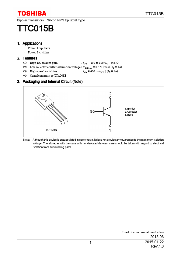
3. Packaging and Internal Circuit (Note)
1. Emitter 2. Collector 3. Base
TO-126N
Note: Although this device is encapsulated in epoxy resin, it does not provide any guarantee to the maximum isolation voltage. Therefore, as with the case with non-isolated devices, care should be taken with regard to electrical isolation from surrounding parts.
Start of mercial production
2013-08
2015-01-22
Rev.1.0
4. Absolute Maximum Ratings (Note) (Ta = 25 unless otherwise specified)
Characteristics
Symbol
Rating
Unit
Collector-base voltage
VCBO
Collector-emitter voltage
VCEX
VCEO
Emitter-base voltage
VEBO
Collector current (DC)
(Note 1)
Collector current...