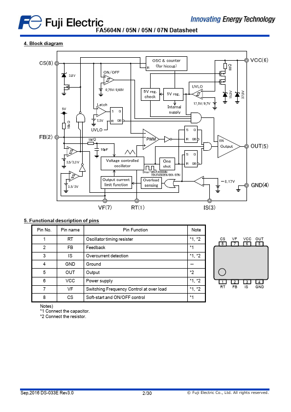
Description
of pins
Pin No.Pin name
Pin Function
1
RT
Oscillator timing resister
2
FB
Feedback
3
IS
Overcurrent detection
4
GND Ground
5
OUT Output
6
VCC Power supply
7
VF
Switching Frequency Control at over load
8
CS
Soft-start and ON/OFF control
Notes)
1 Connect the capacitor.
2 Connect the resistor.
1,
2
1
1,
2 -
2
1,
2
1,
2
1
CS VF VCC OUT
8
7
6
5
1
2
3
4
RT FB IS GND
Sep,2016 DS-033E Rev3.0
2 /30
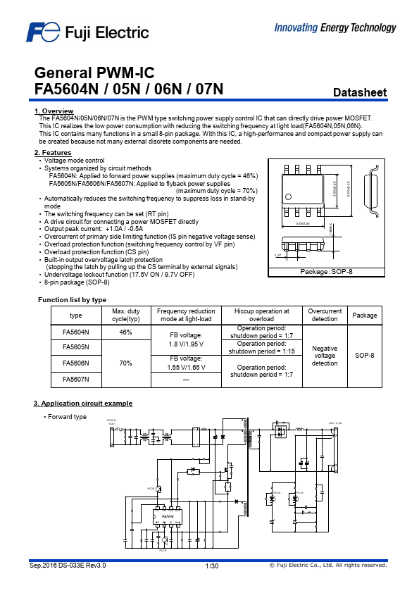
Features
- Voltage mode control.
- Systems organized by circuit methods FA5604N: Applied to forward power supplies (maximum duty cycle = 46%) FA5605N/FA5606N/FA5607N: Applied to flyback power supplies (maximum duty cycle = 70%).
- Automatically reduces the switching frequency to suppress loss in stand-by mode.
- The switching frequency can be set (RT pin).
- A drive circuit for connecting a power MOSFET directly.
- Output peak current: +1.0A / -0.5A.
- Ov.
 FA5604N-Fuji.pdf