Datasheet Details
| Part number | MM1174 |
|---|---|
| Manufacturer | MITSUMI ELECTRIC |
| File Size | 63.96 KB |
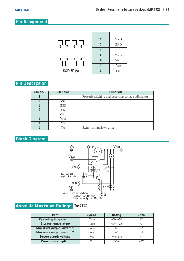
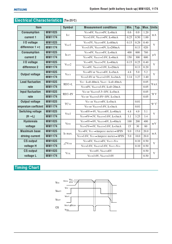
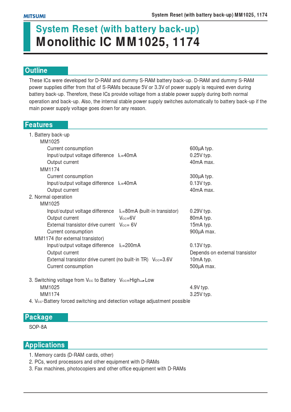
| Description | (MM1025 / MM1174) System Reset (with battery back-up) Monolithic IC |
| Datasheet |
 MM1174 Datasheet MM1174 Datasheet
|
|
|
| Part number | MM1174 |
|---|---|
| Manufacturer | MITSUMI ELECTRIC |
| File Size | 63.96 KB |
| Description | (MM1025 / MM1174) System Reset (with battery back-up) Monolithic IC |
| Datasheet |
MM1174 Datasheet
|
|
|
|
Pin No.
📁 Similar Datasheet