Datasheet Details
| Part number | MAX5105 |
|---|---|
| Manufacturer | Maxim |
| File Size | 523.26 KB |
| Description | Nonvolatile / Quad / 8-Bit DACs |
| Datasheet |
 MAX5105 Datasheet MAX5105 Datasheet
|
|
|
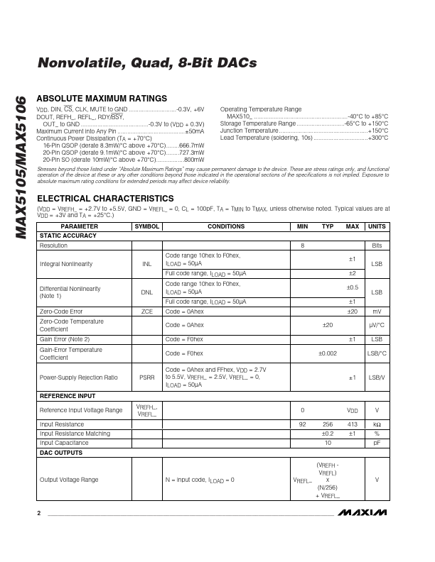
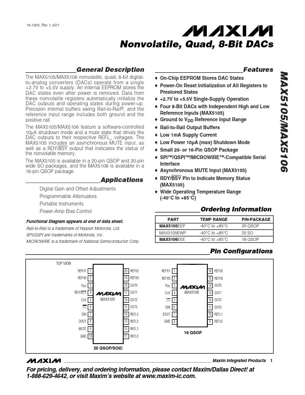
The MAX5105/MAX5106 nonvolatile, quad, 8-bit digitalto-analog converters (DACs) operate from a single +2.7V to +5.5V supply.
An internal EEPROM stores the DAC states even after power is removed.
| Part number | MAX5105 |
|---|---|
| Manufacturer | Maxim |
| File Size | 523.26 KB |
| Description | Nonvolatile / Quad / 8-Bit DACs |
| Datasheet |
MAX5105 Datasheet
|
|
|
|