Datasheet Details
| Part number | MC1496B, MC1496 |
|---|---|
| Manufacturer | Motorola |
| File Size | 245.18 KB |
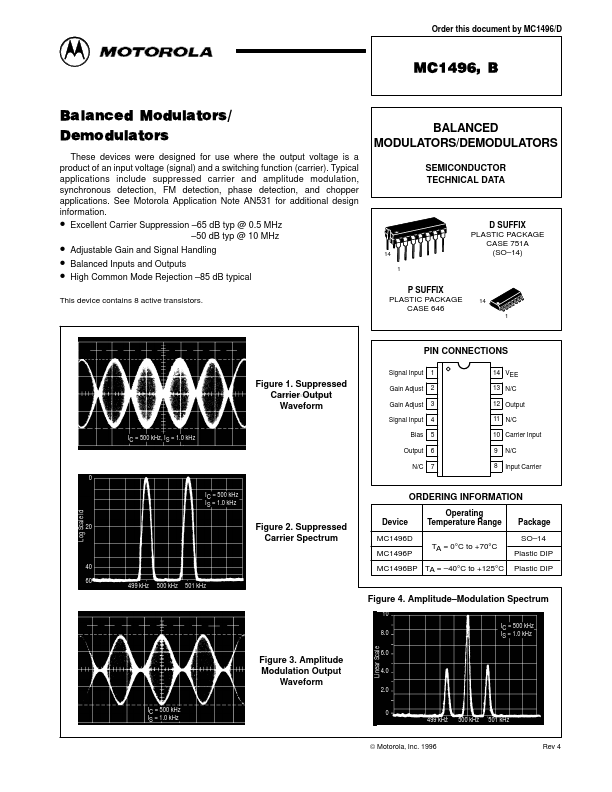
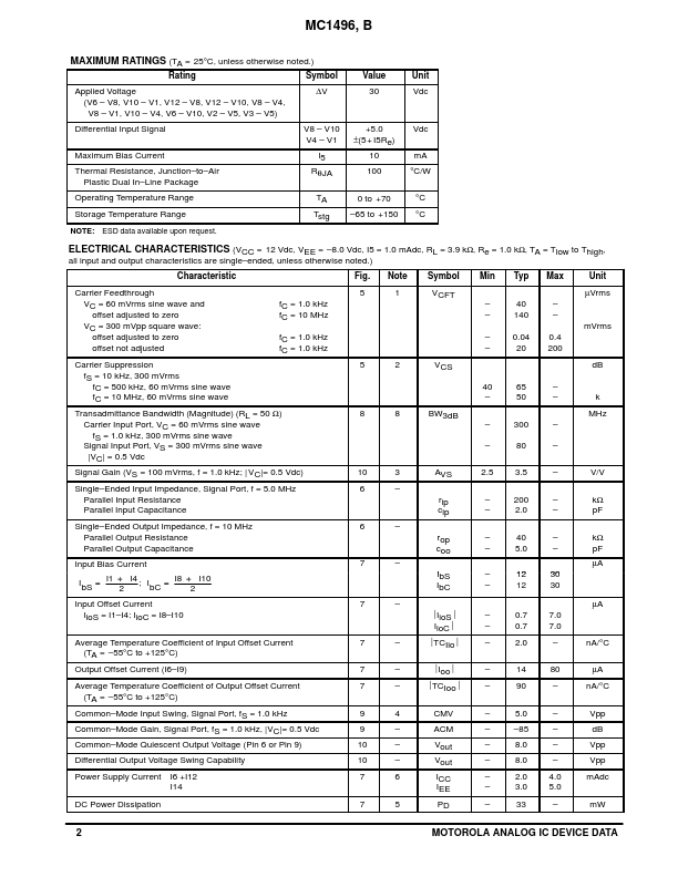
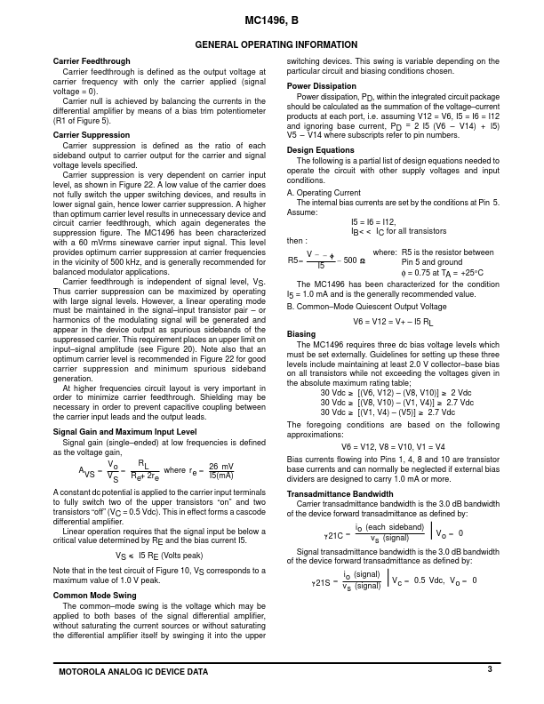
| Description | BALANCED MODULATORS/DEMODULATORS |
| Datasheet |
 MC1496_Motorola.pdf MC1496_Motorola.pdf
|
| Note |
This datasheet PDF includes multiple part numbers: MC1496B, MC1496. Please refer to the document for exact specifications by model. |