Description
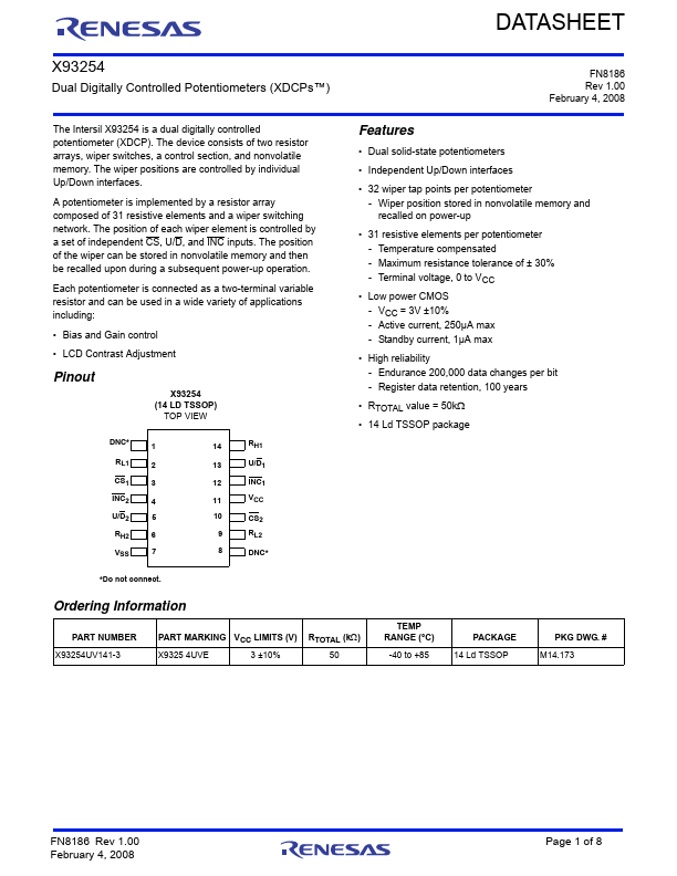
TSSOP 1 2 3 4 5 6 7 8 9 10 11 12 13 14
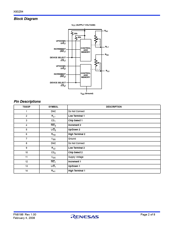
VCC (SUPPLY VOLTAGE)
UP/DOWN (U/D1)
INCREMENT (INC1)
DEVICE SELECT (CS1)
UP/DOWN (U/D2)
INCREMENT (INC2)
DEVICE SELECT (CS2)
30k 30k CONTROL AND MEMORY
CONTROL AND
MEMORY
VSS (Ground)
SYMBOL
DNC
RL1 CS1 INC2 U/D2 RH2 VSS DNC
RL2 CS2 VCC INC1 U/D1 RH1
Do Not Connect Low Terminal 1 Chip Select 1 Increment 2 Up/Down 2 High Terminal 2 Ground Do Not Connect Low Terminal 2 Chip Select 2 Supply Voltage Increment 1 Up/Down 1 High Terminal 1
RH1 RL1 RH2 RL2
D
Features
- Dual solid-state potentiometers.
- Independent Up/Down interfaces.
- 32 wiper tap points per potentiometer - Wiper position stored in nonvolatile memory and recalled on power-up.
- 31 resistive elements per potentiometer - Temperature compensated - Maximum resistance tolerance of ± 30% - Terminal voltage, 0 to VCC.
- Low power CMOS - VCC = 3V ±10% - Active current, 250µA max - Standby current, 1µA max.
- High reliability - Endurance 200,000 data chan.
 X93254-Renesas.pdf