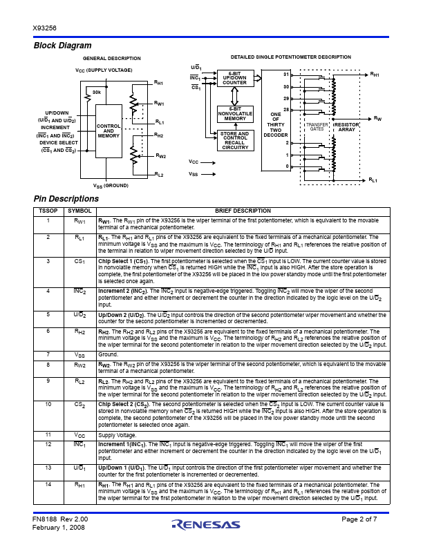
Description
VCC (SUPPLY VOLTAGE)
30k
UP/DOWN
(U/D1 AND U/D2) INCREMENT
(INC1 AND INC2) DEVICE SELECT (CS1 AND CS2)
CONTROL AND
MEMORY
RH1
RW1 RL1 RH2
RW2
VSS (GROUND)
RL2
U/D1 INC1 CS1
VCC VSS
DETAILED SINGLE POTENTIOMETER DESCRIPTION
5-BIT UP/DOWN COUNTER
5-BIT NONVOLATILE
MEMORY STORE AND
CONTROL RECALL CIRCUITRY
31
30
29 28 ONE OF THIRTY TWO DECODER
2
1
0
RH1
TRANSFER GATES
RESISTOR ARRAY
RW
RL1
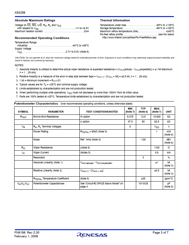
Pin Descriptions
TSSOP 1 2
3
4
5 6
7 8 9
10
11 12
13 14
SYMBOL RW1 RL1
CS1
INC2
U/D2 RH2
VSS
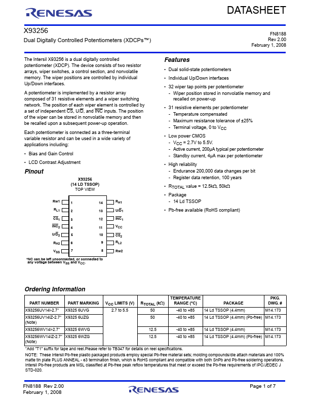
Features
- Dual solid-state potentiometers.
- Individual Up/Down interfaces.
- 32 wiper tap points per potentiometer - Wiper position stored in nonvolatile memory and recalled on power-up.
- 31 resistive elements per potentiometer - Temperature compensated - Maximum resistance tolerance of ±25% - Terminal voltage, 0 to VCC.
- Low power CMOS - VCC = 2.7V to 5.5V. - Active current, 200µA typical per potentiometer - Standby current, 4µA max per potentiometer.
- Hig.
 X93256-Renesas.pdf